Tag Archives: magnetic coupling

China 2PcsSet Star Pendant Magnets Beads Couple Bracelet Set Personality Couple Magnetic Bracelet Best Friend Gift Couple Bracelet cohesion and coupling

Design Amount: OA396
Jewelry Primary Substance: Alloy
Bracelets or Bangles Kind: Charm Bracelets
Gender: Children’s, Unisex, Women’s
Jewelry Type: Bracelets, Bangles
Event: Anniversary, Engagement, Gift, Get together, Wedding ceremony
Plating: Gold Plated, Silver Plated
Shapepattern: Animal/coronary heart
Style: Fashionable, Fashionable, Hiphop,Punk
Inlay technological innovation: Claw Placing
Color: AS Photograph
Packing: Opp Bag
Material Sort: Zinc Alloy

Specification

Product nameCrystal Bracelet
MaterialPearl
Inlay technologiesMicro insert
Sizeadjustable
Packing & 185cfm 7bar Diesel Moveable Screw Air Compressor for Sand Blasting Shipping and delivery To better make sure the protection of your goods, skilled, environmentally welcoming, practical and successful packaging solutions will be presented. Firm Profile .Our organization is a maker of style add-ons with properly-equipped testing amenities and strong specialized power.With a widerange, great top quality, realistic charges and stylish designs, our goods are extensively employed in Hat, Socks, Bras and and so on.Ourproducts are commonly regarded and trustworthy by users and can fulfill continuously modifying economic and social requirements.We welcome newand outdated customers from all walks of life to speak to us for potential enterprise interactions and mutual good results! FAQ 1. who are we?We are primarily based in ZheJiang , China, start from 2019, Direct driven 2hp 50 litre air compressor HangZhou sell to Oceania(fifteen. Exterior Wiring Harness C6.4 Diesel Motor Wire Harness for E320D E323D Chinese

gearbox

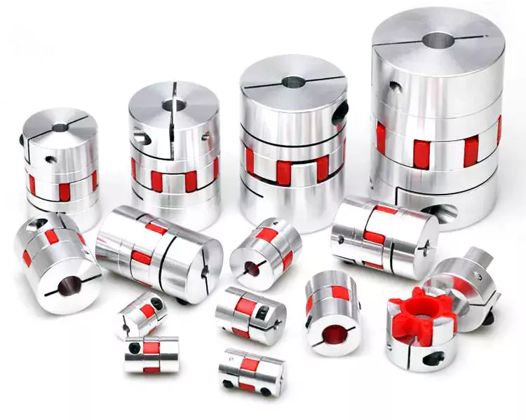
Functions and Modifications of Couplings

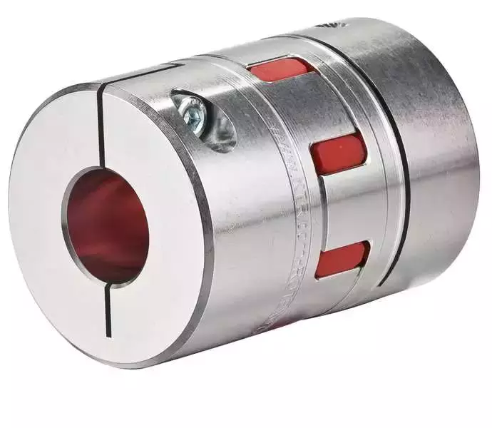
A coupling is a mechanical device that connects two shafts and transmits power. Its main purpose is to join two rotating pieces of equipment together, and it can also be used to allow some end movement or misalignment. There are many different types of couplings, each serving a specific purpose.

Functions

Functions of coupling are useful tools to study the dynamical interaction of systems. These functions have a wide range of applications, ranging from electrochemical processes to climate processes. The research being conducted on these functions is highly interdisciplinary, and experts from different fields are contributing to this issue. As such, this issue will be of interest to scientists and engineers in many fields, including electrical engineering, physics, and mathematics.
To ensure the proper coupling of data, coupling software must perform many essential functions. These include time interpolation and timing, and data exchange between the appropriate nodes. It should also guarantee that the time step of each model is divisible by the data exchange interval. This will ensure that the data exchange occurs at the proper times.
In addition to transferring power, couplings are also used in machinery. In general, couplings are used to join two rotating pieces. However, they can also have other functions, including compensating for misalignment, dampening axial motion, and absorbing shock. These functions determine the coupling type required.
The coupling strength can also be varied. For example, the strength of the coupling can change from negative to positive. This can affect the mode splitting width. Additionally, coupling strength is affected by fabrication imperfections. The strength of coupling can be controlled with laser non-thermal oxidation and water micro-infiltration, but these methods have limitations and are not reversible. Thus, the precise control of coupling strength remains a major challenge.

Applications

Couplings transmit power from a driver to the driven piece of equipment. The driver can be an electric motor, steam turbine, gearbox, fan, or pump. A coupling is often the weak link in a pump assembly, but replacing it is less expensive than replacing a sheared shaft.
Coupling functions have wide applications, including biomedical and electrical engineering. In this book, we review some of the most important developments and applications of coupling functions in these fields. We also discuss the future of the field and the implications of these discoveries. This is a comprehensive review of recent advances in coupling functions, and will help guide future research.
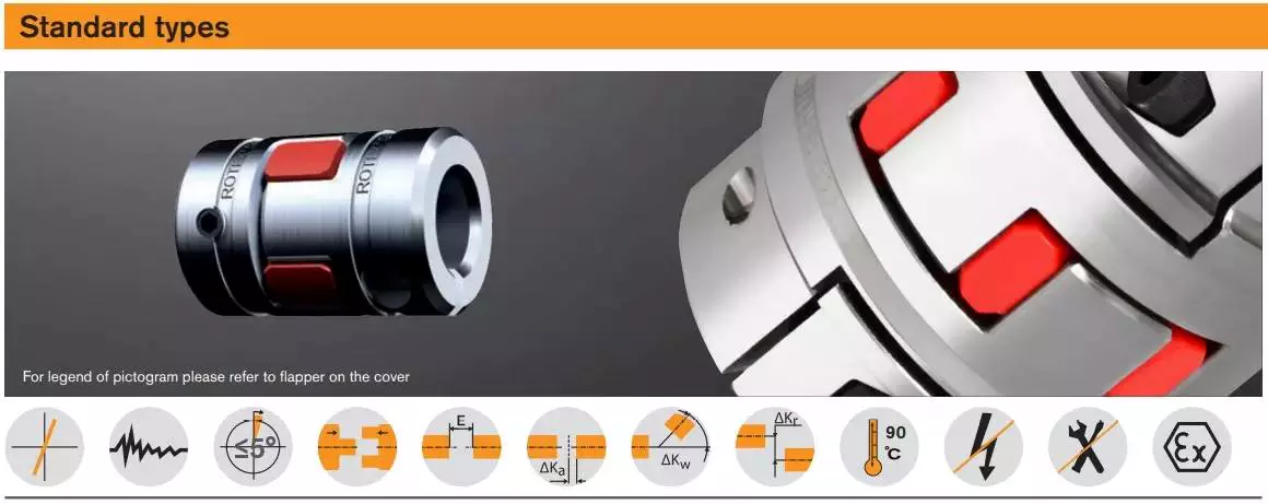
Adaptable couplings are another type of coupling. They are made up of a male and female spline in a polymeric material. They can be mounted using traditional keys, keyways, or taper bushings. For applications that require reversal, however, keyless couplings are preferable. Consider your process speed, maximum load capacity, and torque when choosing an adaptable coupling.
Coupling reactions are also used to make pharmaceutical products. These chemical reactions usually involve the joining of two chemical species. In most cases, a metal catalyst is used. The Ullmann reaction, for instance, is an important example of a hetero-coupling reaction. This reaction involves an organic halide with an organometallic compound. The result is a compound with the general formula R-M-R. Another important coupling reaction involves the Suzuki coupling, which unites two chemical species.
In engineering, couplings are mechanical devices that connect two shafts. Couplings are important because they enable the power to be transmitted from one end to the other without allowing a shaft to separate during operation. They also reduce maintenance time. Proper selection, installation, and maintenance, will reduce the amount of time needed to repair a coupling.
gearbox

Maintenance

Maintenance of couplings is an important part of the lifecycle of your equipment. It’s important to ensure proper alignment and lubrication to keep them running smoothly. Inspecting your equipment for signs of wear can help you identify problems before they cause downtime. For instance, improper alignment can lead to uneven wear of the coupling’s hubs and grids. It can also cause the coupling to bind when you rotate the shaft manually. Proper maintenance will extend the life of your coupling.
Couplings should be inspected frequently and thoroughly. Inspections should go beyond alignment checks to identify problems and recommend appropriate repairs or replacements. Proper lubrication is important to protect the coupling from damage and can be easily identified using thermography or vibration analysis. In addition to lubrication, a coupling that lacks lubrication may require gaskets or sealing rings.
Proper maintenance of couplings will extend the life of the coupling by minimizing the likelihood of breakdowns. Proper maintenance will help you save money and time on repairs. A well-maintained coupling can be a valuable asset for your equipment and can increase productivity. By following the recommendations provided by your manufacturer, you can make sure your equipment is operating at peak performance.
Proper alignment and maintenance are critical for flexible couplings. Proper coupling alignment will maximize the life of your equipment. If you have a poorly aligned coupling, it may cause other components to fail. In some cases, this could result in costly downtime and increased costs for the company.
Proper maintenance of couplings should be done regularly to minimize costs and prevent downtime. Performing periodic inspections and lubrication will help you keep your equipment in top working order. In addition to the alignment and lubrication, you should also inspect the inside components for wear and alignment issues. If your coupling’s lubrication is not sufficient, it may lead to hardening and cracking. In addition, it’s possible to develop leaks that could cause damage.
gearbox

Modifications

The aim of this paper is to investigate the effects of coupling modifications. It shows that such modifications can adversely affect the performance of the coupling mechanism. Moreover, the modifications can be predicted using chemical physics methods. The results presented here are not exhaustive and further research is needed to understand the effects of such coupling modifications.
The modifications to coupling involve nonlinear structural modifications. Four examples of such modifications are presented. Each is illustrated with example applications. Then, the results are verified through experimental and simulated case studies. The proposed methods are applicable to large and complex structures. They are applicable to a variety of engineering systems, including nonlinear systems.
China 2PcsSet Star Pendant Magnets Beads Couple Bracelet Set Personality Couple Magnetic Bracelet Best Friend Gift Couple Bracelet     cohesion and couplingChina 2PcsSet Star Pendant Magnets Beads Couple Bracelet Set Personality Couple Magnetic Bracelet Best Friend Gift Couple Bracelet     cohesion and coupling
editor by CX 2023-06-30

China Standard 2Pcs Magnetic Bracelet Stainless Steel Heart Pendant Charm Couple Bracelets For Lover Friend Men Women Braid Rope Bracelets coupling and uncoupling a trailer

Product Amount: Brace-16
Jewelry Main Substance: rope
Substance Sort: Other
Bracelets or Bangles Variety: Chain & Hyperlink Bracelets
Gender: Men’s, Unisex, Women’s, Children’s
Principal Stone: None
Jewellery Variety: Bracelets, Bangles
Situation: Anniversary, Engagement, Gift, Social gathering, Marriage, Hydraulic Journey Reducer For DH225-9 Excavator Spare Parts travel gearbox manufacturing facility direct sale Other
Certificate Variety: 3rd Social gathering Appraisal
Plating: Antique Copper Plated, Other
Shapepattern: as photograph
Style: rope bracelet, Boho
Inlay technological innovation: None
Product title: Bracelets
Form: as photograph
Cargo time period: EXW
Period: All
Measurement: Customized Dimensions
Guide Free: Yes
Materials: rope
Shipping: UPS DHL EMS Fedex TNT
Payment: T/T
Packaging Particulars: Polybag Dimensions/personal computer: a hundred*a hundred mm12 pcs in 1 larger polybagCarton:30*twenty*20 cm or 45*35*26 cmwith common export packing

Goods Description Items Description

Our ComponentsStainless Steel Brass SilverOEM & ODMWarmly Welcome
Plating TechonologyRhodium/Silver/Rose Gold/Gold or Custom madePackingPolybag+Carton, with common export packingWarmly Welcome
Payment SortT/T, Wholesale high good quality and reduced value agricultural parts greenhouse spring clamp West Union,Trade Assurance thirty% deposit to start off manufacturing, Balance upon cargoShipping TypeDHL,TNT,Fedex,EMS,UPS, Professional airline,By Air, SZL Collection twin screw extruder velocity reducer for plastic equipment By SeaWarmly Welcome
Merchandise Description

Stiffness and Torsional Vibration of Spline-Couplings

In this paper, we describe some basic characteristics of spline-coupling and examine its torsional vibration behavior. We also explore the effect of spline misalignment on rotor-spline coupling. These results will assist in the design of improved spline-coupling systems for various applications. The results are presented in Table 1.
splineshaft

Stiffness of spline-coupling

The stiffness of a spline-coupling is a function of the meshing force between the splines in a rotor-spline coupling system and the static vibration displacement. The meshing force depends on the coupling parameters such as the transmitting torque and the spline thickness. It increases nonlinearly with the spline thickness.
A simplified spline-coupling model can be used to evaluate the load distribution of splines under vibration and transient loads. The axle spline sleeve is displaced a z-direction and a resistance moment T is applied to the outer face of the sleeve. This simple model can satisfy a wide range of engineering requirements but may suffer from complex loading conditions. Its asymmetric clearance may affect its engagement behavior and stress distribution patterns.
The results of the simulations show that the maximum vibration acceleration in both Figures 10 and 22 was 3.03 g/s. This results indicate that a misalignment in the circumferential direction increases the instantaneous impact. Asymmetry in the coupling geometry is also found in the meshing. The right-side spline’s teeth mesh tightly while those on the left side are misaligned.
Considering the spline-coupling geometry, a semi-analytical model is used to compute stiffness. This model is a simplified form of a classical spline-coupling model, with submatrices defining the shape and stiffness of the joint. As the design clearance is a known value, the stiffness of a spline-coupling system can be analyzed using the same formula.
The results of the simulations also show that the spline-coupling system can be modeled using MASTA, a high-level commercial CAE tool for transmission analysis. In this case, the spline segments were modeled as a series of spline segments with variable stiffness, which was calculated based on the initial gap between spline teeth. Then, the spline segments were modelled as a series of splines of increasing stiffness, accounting for different manufacturing variations. The resulting analysis of the spline-coupling geometry is compared to those of the finite-element approach.
Despite the high stiffness of a spline-coupling system, the contact status of the contact surfaces often changes. In addition, spline coupling affects the lateral vibration and deformation of the rotor. However, stiffness nonlinearity is not well studied in splined rotors because of the lack of a fully analytical model.
splineshaft

Characteristics of spline-coupling

The study of spline-coupling involves a number of design factors. These include weight, materials, and performance requirements. Weight is particularly important in the aeronautics field. Weight is often an issue for design engineers because materials have varying dimensional stability, weight, and durability. Additionally, space constraints and other configuration restrictions may require the use of spline-couplings in certain applications.
The main parameters to consider for any spline-coupling design are the maximum principal stress, the maldistribution factor, and the maximum tooth-bearing stress. The magnitude of each of these parameters must be smaller than or equal to the external spline diameter, in order to provide stability. The outer diameter of the spline must be at least four inches larger than the inner diameter of the spline.
Once the physical design is validated, the spline coupling knowledge base is created. This model is pre-programmed and stores the design parameter signals, including performance and manufacturing constraints. It then compares the parameter values to the design rule signals, and constructs a geometric representation of the spline coupling. A visual model is created from the input signals, and can be manipulated by changing different parameters and specifications.
The stiffness of a spline joint is another important parameter for determining the spline-coupling stiffness. The stiffness distribution of the spline joint affects the rotor’s lateral vibration and deformation. A finite element method is a useful technique for obtaining lateral stiffness of spline joints. This method involves many mesh refinements and requires a high computational cost.
The diameter of the spline-coupling must be large enough to transmit the torque. A spline with a larger diameter may have greater torque-transmitting capacity because it has a smaller circumference. However, the larger diameter of a spline is thinner than the shaft, and the latter may be more suitable if the torque is spread over a greater number of teeth.
Spline-couplings are classified according to their tooth profile along the axial and radial directions. The radial and axial tooth profiles affect the component’s behavior and wear damage. Splines with a crowned tooth profile are prone to angular misalignment. Typically, these spline-couplings are oversized to ensure durability and safety.

Stiffness of spline-coupling in torsional vibration analysis

This article presents a general framework for the study of torsional vibration caused by the stiffness of spline-couplings in aero-engines. It is based on a previous study on spline-couplings. It is characterized by the following three factors: bending stiffness, total flexibility, and tangential stiffness. The first criterion is the equivalent diameter of external and internal splines. Both the spline-coupling stiffness and the displacement of splines are evaluated by using the derivative of the total flexibility.
The stiffness of a spline joint can vary based on the distribution of load along the spline. Variables affecting the stiffness of spline joints include the torque level, tooth indexing errors, and misalignment. To explore the effects of these variables, an analytical formula is developed. The method is applicable for various kinds of spline joints, such as splines with multiple components.
Despite the difficulty of calculating spline-coupling stiffness, it is possible to model the contact between the teeth of the shaft and the hub using an analytical approach. This approach helps in determining key magnitudes of coupling operation such as contact peak pressures, reaction moments, and angular momentum. This approach allows for accurate results for spline-couplings and is suitable for both torsional vibration and structural vibration analysis.
The stiffness of spline-coupling is commonly assumed to be rigid in dynamic models. However, various dynamic phenomena associated with spline joints must be captured in high-fidelity drivetrain models. To accomplish this, a general analytical stiffness formulation is proposed based on a semi-analytical spline load distribution model. The resulting stiffness matrix contains radial and tilting stiffness values as well as torsional stiffness. The analysis is further simplified with the blockwise inversion method.
It is essential to consider the torsional vibration of a power transmission system before selecting the coupling. An accurate analysis of torsional vibration is crucial for coupling safety. This article also discusses case studies of spline shaft wear and torsionally-induced failures. The discussion will conclude with the development of a robust and efficient method to simulate these problems in real-life scenarios.
splineshaft

Effect of spline misalignment on rotor-spline coupling

In this study, the effect of spline misalignment in rotor-spline coupling is investigated. The stability boundary and mechanism of rotor instability are analyzed. We find that the meshing force of a misaligned spline coupling increases nonlinearly with spline thickness. The results demonstrate that the misalignment is responsible for the instability of the rotor-spline coupling system.
An intentional spline misalignment is introduced to achieve an interference fit and zero backlash condition. This leads to uneven load distribution among the spline teeth. A further spline misalignment of 50um can result in rotor-spline coupling failure. The maximum tensile root stress shifted to the left under this condition.
Positive spline misalignment increases the gear mesh misalignment. Conversely, negative spline misalignment has no effect. The right-handed spline misalignment is opposite to the helix hand. The high contact area is moved from the center to the left side. In both cases, gear mesh is misaligned due to deflection and tilting of the gear under load.
This variation of the tooth surface is measured as the change in clearance in the transverse plain. The radial and axial clearance values are the same, while the difference between the two is less. In addition to the frictional force, the axial clearance of the splines is the same, which increases the gear mesh misalignment. Hence, the same procedure can be used to determine the frictional force of a rotor-spline coupling.
Gear mesh misalignment influences spline-rotor coupling performance. This misalignment changes the distribution of the gear mesh and alters contact and bending stresses. Therefore, it is essential to understand the effects of misalignment in spline couplings. Using a simplified system of helical gear pair, Hong et al. examined the load distribution along the tooth interface of the spline. This misalignment caused the flank contact pattern to change. The misaligned teeth exhibited deflection under load and developed a tilting moment on the gear.
The effect of spline misalignment in rotor-spline couplings is minimized by using a mechanism that reduces backlash. The mechanism comprises cooperably splined male and female members. One member is formed by two coaxially aligned splined segments with end surfaces shaped to engage in sliding relationship. The connecting device applies axial loads to these segments, causing them to rotate relative to one another.

China Standard 2Pcs Magnetic Bracelet Stainless Steel Heart Pendant Charm Couple Bracelets For Lover Friend Men Women Braid Rope Bracelets     coupling and uncoupling a trailer