Product Description
- Customized Stainless Steel/Carbon Steel/steel Lost Wax Casting/precision casting steel connector/pipe fitting/base/gear/cap/washer/bracket/flange/coupling
- Material:
Stainless Steel: JIS SCS1, SCS2, SCS13, SCS13L, SCS14, SCS14L/ DIN G-X7Cr13, G-X20Cr14, G-X6CrNi18 9, G-X6CrNiMo18 10, 1.3955, 1.4308, 1.4408, 1.4581 / ASTM/AISI CA-15, CA-40, CF-3/304L, CF-3M/316L, CF-8/304, CF-8M/316, etc Carbon Steel: JIS SC450, SCC5 / DIN GS-45, GS-60 / ASTM WCB, 450-240, 80-40, etc Alloy Steel: JIS SCW480, SCSiMn2, SCCrMn3 / DIN GS-20Mn5, GS-37MnSi5, GS-34CrMo4, etc Heat Resistance Steel: JIS SCH13, SCH21, SCH24/ DIN G-X15CrNiSi25 20 1.4840,G-X45CrNiSi35 25 1.4857 / ASTM HN, HK30, HK, HK40, HHM HP, HT Bronze or Copper: JIS BC6, ALBC6, etc Other materials Carbon Steel, Alloy Steel, Hight Manganese Steel, Tool steel, Heat-resistant Steel, Al-Si Alloy, etc also available according to customer’s request.
- Required documents for offer to be provided by customer:
Drawings with formats of IGS (3D), DWG or DXF (Auto CAD 2D), PDF, JPG
Standard of material (Preferable to provide Element Percentage of C, Si, Mn, P, S, etc and Physical/Machanical Properties of the material)
Technical requirements
Unit Weight of Rough Casting
Production technology: Lost-wax casting/investment casting
- Main production equipment:
Vertical wax-injectors
Sand glueing tanks
Wax-evaporator
Intermediate frequency electrical induction furnaces
Spectrum analyzer
Shot blast machines
Heat treatment furnaces
Heat treatment water tank
Acid solution and water cleaning tank
Buffing / polishing machines / Electrical polishing
- Unit weight: 1.2g~80,000g per piece
- Other details:
Taper hole, deep hole, bent hole D>Ø2mm L=1D
Minimum outside radius R0.3mm, minimum inside radius R0.5mm
Minimum thickness of 1.5mm, some parts with minimum thickness of 0.8mm
- Tolerance of dimension for cast:
Dimension Range (mm) Common Tolerance Special Tolerance < 25 +/- 0.25 mm +/- 0.13 mm 25 ~ 50 +/- 0.40 mm +/- 0.25 mm 50 ~ 100 +/- 0.80 mm +/- 0.50 mm > 100 +/- 1 % +/- 0.5 % - Minimum order: No limit
- Delivery: Within 30 working days after signing of contract and confirmation of samples by client
- Technological process:
- Workshop:
- Some Products:
- Testing equipments:
- Shipments:
- Company information:
- Certifications:
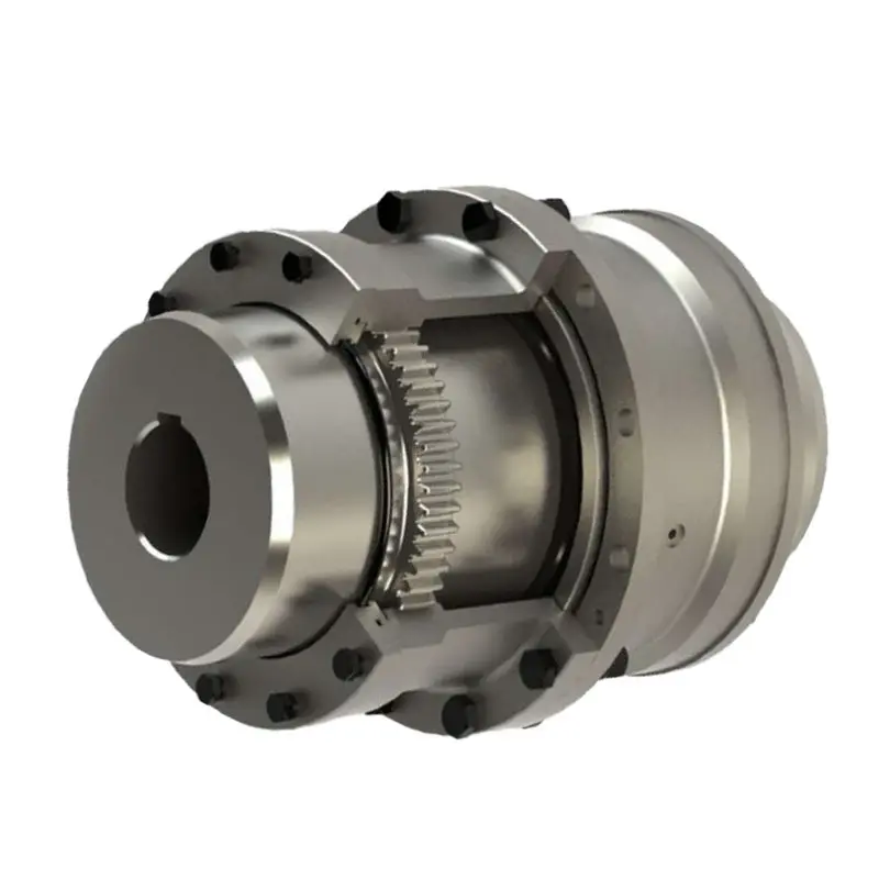
Handling Misalignment with Gear Couplings
Gear couplings are designed to accommodate certain degrees of misalignment between shafts, making them suitable for applications where some flexibility is required. They can handle three main types of misalignment:
- Angular Misalignment: This type of misalignment occurs when the axes of the two connected shafts are not parallel but intersect at a small angle. Gear couplings can handle a moderate amount of angular misalignment, typically up to a few degrees, without sacrificing performance.
- Parallel Misalignment: Parallel misalignment refers to a situation where the two connected shafts are offset in parallel but remain parallel to each other. Gear couplings can accommodate a certain amount of parallel misalignment, but it is generally limited to a fraction of the coupling’s overall length.
- Axial Misalignment: Axial misalignment happens when the two shafts are offset along the axis of rotation. Gear couplings can handle limited axial misalignment, but it is essential to ensure that the coupling’s end float or end-play is correctly set to prevent axial loading on connected equipment.
It is important to note that while gear couplings can handle some degree of misalignment, excessive misalignment can lead to premature wear and failure. Regular maintenance and proper installation are crucial to ensuring that gear couplings perform optimally and have a longer service life.


editor by CX 2023-09-27