Leaf Chains are created for large load, slow velocity stress linkage applications. Often they are really specifi ed for reciprocating motion lifting units this kind of as fork lifts or cranes. These chains are usually provided to a specifi c length and therefore are connected to a clevis block at just about every finish. The clevis might accommodate male ends (inside or from time to time called “articulating” backlinks) or female ends (outdoors or the links within the pin link) as necessary (see illustration below)
Leaf chains are available in 3 series; AL (light duty), BL (heavy duty), or LL (European typical). For new selections we endorse the BL series in preference towards the AL series since the latter continues to be discontinued as a recognized ASME/ANSI normal series chain. BL series chains are created in accordance with all the ASME/ANSI B29.eight American Leaf Chain Standard. 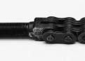 LL series chains are created in accordance using the ISO 606 worldwide leaf chain conventional.
A chain with an even amount of pitches often features a one male and one female finish. It can be far more common to have the chain possess an odd number of pitches in which case the the two ends are going to be either male (most common) or female (significantly less com-mon). When ordering lengths with an odd amount of pitches male ends are supplied unless otherwise noted. Clevis pins, ordinarily with cotters at each and every finish, are utilised to connect male chain ends to female clevis blocks. Chains with female ends are frequently (but not usually) linked towards the clevis block having a cottered style connecting link. The connecting hyperlink is the female end part in this instance.
Leaf Chain Choice
Make use of the following formula to confirm the choice of leaf chain:
Minimal Ultimate Power > T x DF x SF
T: Calculated Maximum Chain Tension
DF: Duty Factor
SF: Service Component
Note that the optimum allowable chain velocity for leaf chains is 100ft per minute.