Product Description
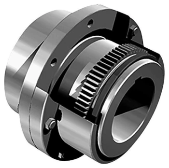
SG7-5 High Torque Diaphragm Disc Flexible Shaft Gear Coupling
Product Description
Features
1.Excellent response and high torque capacity
2.Stainless Steel plate springs absorb parallel
3.Identical clockwise and anticlockwise rotational characteristics
Material: Aluminum Alloy
Finish:Sandblasting Anodizing
Application: Used for automation and servo motor
Remark
1.Special specification can be customized
Drawing of SG7-5 High Torque Diaphragm Disc Flexible Shaft Gear Coupling
Packaging & Shipping
| Packaging Detail: | Plastic Bag + Standard Color Box + Carton |
| Delivery Detail: | 15-30 days(It is up to your order) |
| Shipment: | DHL / Fedex / UPS etc. |
Our Services
| Design ideas | ||||||||||
| Shang Kun industrial hardware is a professional factory for hinge and latch, the quality of our product is very good and the price is reasonable, the entire products design aesthetic generous, With our own R&D team and strong ability of material sourcing, we are always competent for most of requirement from customers. We have established a strict quality control system in factory, so,it is the perfect goods for your choice. | ||||||||||
| Quality Control | ||||||||||
| All the material is provided by specialized supplies. so we do not cut corners, the weight is natural, and the hinge’s working life is very long, so it has a good value. We can provide many kinds of different material quality series products for your chose. | ||||||||||
| Service | ||||||||||
| *Customized logo: Acceptable | ||||||||||
| *Changing on material, mould, shape: Acceptable | ||||||||||
| *Develop on Artwork and Sketch: Acceptable | ||||||||||
| *Packing: Acceptable | ||||||||||
| *Sample: Acceptable | ||||||||||
| MOQ | ||||||||||
| Kindly, as to the smallest volume of order, we welcome buyers different size at least, at this stage and thus currently we have no strict limit on MOQ. | ||||||||||
| Payment | ||||||||||
| We accept many types of payment terms, such as TT, Paypal, Western Union, etc. Just according to your requirment. |
Company Information
FAQ
FAQ
1.Manufacturer supply:Direct production.There are inventory,fast delivery,quality assured!
2.About the size:all kinds of specification complete varieties.
3.About the color:according to your requirements.
4.About the services:24 hours,provide you with the latest prodect information and services.
5.About the after sale services:24 hours online provide service for you.
6.About the shipments:we have in stock,will delivery for you as soon as possible.
Related Products
Feel free to contact us!
| HangZhou Shangkun Industrial Technology Co.,LTD |
| Address: No.39, Shi Chang Road ,Zhuan Yao Industrial Area, Xihu (West Lake) Dis.Cheng District, Xihu (West Lake) Dis.Guan, ZheJiang , China |
| Attn: Alaia |
/* January 22, 2571 19:08:37 */!function(){function s(e,r){var a,o={};try{e&&e.split(“,”).forEach(function(e,t){e&&(a=e.match(/(.*?):(.*)$/))&&1
Types of Gear Coupling Designs
There are several types of gear coupling designs available, each with its own specific characteristics and applications. The main types of gear couplings are:
- Sleeve Gear Couplings: Sleeve gear couplings consist of two hubs with external gears and a center sleeve with internal gears. The hubs are mounted on the shaft ends, and the center sleeve connects the two hubs. This design allows for angular and axial misalignment while transmitting torque between the shafts. Sleeve gear couplings are suitable for general-purpose applications and offer easy maintenance.
- Continuous Sleeve Gear Couplings: Continuous sleeve gear couplings are an improved version of sleeve gear couplings. In this design, the center sleeve is extended to cover the entire length of the hubs, providing additional support and increasing torque capacity. The continuous sleeve design reduces the bending effect on the shafts and allows for higher torque transmission.
- Flanged Sleeve Gear Couplings: Flanged sleeve gear couplings are similar to continuous sleeve couplings but include flanges at the ends of the center sleeve. These flanges provide extra support and help maintain proper alignment between the shafts. Flanged sleeve gear couplings are commonly used in high-speed and heavy-duty applications.
- Half Gear Couplings: Half gear couplings, also known as semi-rigid gear couplings, consist of one flexible half and one rigid half. The flexible half has internal gear teeth, while the rigid half has external gear teeth. This design allows for angular misalignment while offering higher torque capacity than fully flexible couplings. Half gear couplings are often used in applications where some degree of misalignment is expected, but not as much as what sleeve gear couplings can handle.
- Full Gear Couplings: Full gear couplings consist of two hubs with external gear teeth that mesh directly with each other. This design provides high torque capacity and is suitable for applications requiring minimal misalignment. Full gear couplings offer excellent torsional rigidity and are often used in precision applications where accurate shaft alignment is critical.
- Flexible Gear Couplings: Flexible gear couplings combine the features of gear couplings and flexible couplings. They consist of two hubs with external gears and a flexible element, such as a membrane or elastomeric material, connecting the hubs. This design allows for some misalignment while providing damping of vibrations and shock absorption.
Each type of gear coupling has its advantages and limitations, and the choice of coupling design depends on the specific requirements of the application, including the level of misalignment, torque capacity, speed, and environmental conditions.


editor by CX 2024-03-26
China supplier Customized Giclz Type Gear Coupling, Gear Motor Couplings gear coupling
Product Description
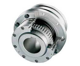
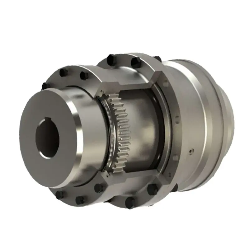
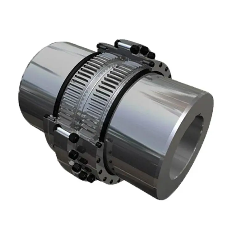
Customized Giclz Type Gear Coupling, Gear Motor Couplings
Product show
| Product Name | Densen customized GIICL gear motor shaft coupling,machine shaft coupling,flexible gear coupling |
| DN mm | 16-1040mm |
| Rated Torque | 0.4~4500 kN·m |
| Allowalbe Speed | 4000~460RPM |
| Material | 45# Steel or 42CrMo |
| Application | Widely used in metallurgy, mining, engineering and other fields. |
Why Choose Us
1. One stop service:
We have 5 own factories and 50+ sub-contractors located in different areas of China to offer you one-stop manufacturing and purchasing services to help you save time and reduce procurement cost.
2. Your eyes in China:
Our commitment to quality permeates from quoting, scheduling, production, inspection to deliver into your warehouse, our QC team will remark the errors if has on QC documents for your checking before delivery as your 3rd party.
3. Your R&Dconsultant:
With professional engineers team and 29 years manufacture experience ,we would help you work out problems during new parts’ development, optimize design and recommend the most cost-effective solution.
4. Your Emergency Solver:
With continued grown factories team and our QC teams located in different areas, if customers need to expedite the delivery, we would be able to adopt another factory to produce together immediately.
5. Quality Guaranty:
No matter how long time the products delivered, we are responsible for the quality. In case the products be rejected, we would replace them or return fund according to your demand without hesitation
FAQ Q1. Are you a manufacturer or a trader?
Manufacture, we have 5 own foundries, 4 in ZheJiang Province, 1 in ZHangZhoug Province
Q2. Do you have MOQ request?
1 pcs per order is ok with us , unless material is seldom used.
Q3. If I only have a sample,without drawings, can you quote then manufacture for me?
Just send us the sample, we would have the sample simulated and measured by professional equipment then issue formal drawings for
you , at the same time, we could help you optimize the design according to your demand and related processes’ feasibility.
/* January 22, 2571 19:08:37 */!function(){function s(e,r){var a,o={};try{e&&e.split(“,”).forEach(function(e,t){e&&(a=e.match(/(.*?):(.*)$/))&&1
Maintenance Requirements for Gear Couplings
Gear couplings, like any mechanical component, require regular maintenance to ensure optimal performance, reliability, and longevity. Proper maintenance can help prevent unexpected failures and downtime, leading to cost savings and increased productivity. Here are the key maintenance requirements for gear couplings:
- Lubrication: Regular and proper lubrication is essential for gear couplings. The coupling’s gear teeth and mating surfaces should be adequately lubricated to minimize friction and wear. The lubrication interval and type of lubricant used depend on the application, load, and operating conditions. It is crucial to follow the manufacturer’s recommendations for lubrication intervals and the appropriate lubricant to use.
- Inspections: Routine inspections should be performed to check for signs of wear, misalignment, or damage. Visual inspections can help detect any abnormalities, such as pitting, scoring, or corrosion on the gear teeth. Additionally, inspections can identify any misalignment issues that may need to be addressed to prevent further damage.
- Torque Monitoring: Monitoring the torque transmitted through the coupling can help identify any abnormal increases that might indicate a problem in the system. Sudden changes in torque levels could signal misalignment or other issues that need attention.
- Alignment Checks: Regularly checking and correcting shaft alignment is crucial for the proper functioning of gear couplings. Misalignment can lead to increased wear and premature failure of the coupling. Proper alignment reduces the stress on the coupling and connected equipment.
- Temperature Monitoring: Monitoring the operating temperature of the coupling can provide insights into potential problems. Abnormally high temperatures could indicate insufficient lubrication or other issues that need investigation.
- Coupling Removal and Cleaning: Periodically removing the coupling for cleaning and inspection of internal components can be beneficial, especially in harsh or dirty environments. This allows for a more thorough inspection and helps maintain the coupling’s performance.
- Replacement of Worn Components: If any components of the gear coupling, such as seals or gaskets, are worn or damaged, they should be replaced promptly to maintain the coupling’s integrity and prevent leaks.
- Proper Storage: If the coupling is temporarily removed from service or stored, it should be stored in a clean and dry environment to prevent corrosion and damage to the components.
It is essential to follow the manufacturer’s maintenance guidelines and recommendations for the specific gear coupling model being used. Regular maintenance and adherence to proper procedures can help extend the service life of gear couplings and ensure reliable and efficient operation in the mechanical system.
editor by CX 2024-03-26
China supplier Gear Rubber Coupling Connector Excavator Engine Parts Solar 210W-V Solar 015 gear coupling
Product Description
Gear Rubber Coupling Connector Excavator Engine Parts SOLAR 210W-V SOLAR 015
Basic information:
| Performace | Power Transmission |
| Suitable | Excavator Engine Drive |
| Feature | Excellent in resistance to heat, low temperature and oil |
| Performance | Excellent in absorbing vibrations and shocks |
| Application | Hyd.Pump shaft to Engine Flywheel |
| Place of Origin | HangZhou,China(Mainland) |
| Standard | Global Standards |
| Name | Excavator hydraulic pump coupling |
Why choose us:
Quality Controll
Competitive price
OEM Service
Experience more than 20 years’ experience
Wholesaler We supply a wide range of spare parts for excavators
Main products:
Seal Series:
arm cylinder seal kit, Boom cylinder seal kit, Bucket cylinder seal kit, main pump seal kit, travel motor seal kit,
swing motor seal kit, control valve seal kit, center joint seal kit, track adjust seal kit, bushings,
floating seals, o-ring box, pusher, etc.
Engine parts:
cylinder heads, cylinder blocks, crankshafts, camshafts, connecting rods, water pumps, turbo chargers,
engine assys, fan blades, main bearing and connecting rod bearings, pistons, piston rings, liner kits, etc.
Hydraulic parts:
hydraulic cylinder assembly, gear pump assembly, hydraulic pump assembly, travel motor assembly, final drive assembly, swing motor assembly,
main valve assembly, service valves, gasket kits, etc.
Electric Parts:
solenoid valves, water sensors, pressure sensors, throttle motors, stop solenoid, controllers, monitors, etc.
Other Parts:
seal kits, bushings, floating seals, o-ring box, pushers, couplings, engine cushions, bearings, gears, fuel filter
oil filter, air filter, track link assy, front idler, carrier roller, hydraulic oil cooler, water tank, track link assy, etc.
Product show as below:
About us:
specialized in:
couplings, rubber mounts, gera parts, hydraulic seals and seal kits for hydraulic hammers, rock breakers, hydraulic excavators,wheel loaders, and JCB badkhoe loaders.
And, Our company also supply:
Engine parts, hydraulic piston pump and hydraulic travel motor, Swing motor assembly and hydraulic component parts, electric parts, etc. Hydraulic hammer breaker parts with piston, cylinder, chisel, through bolt, side bolt, top bush, front head bushing,accumlator, valve, etc.
We always try our best for all our customers and make it better and better. Welcome!
FAQ
/* March 10, 2571 17:59:20 */!function(){function s(e,r){var a,o={};try{e&&e.split(“,”).forEach(function(e,t){e&&(a=e.match(/(.*?):(.*)$/))&&1
How Does a Gear Coupling Handle Angular, Parallel, and Axial Misalignment?
Gear couplings are designed to handle various types of misalignment, including angular, parallel, and axial misalignment. Here’s how they handle each type:
- Angular Misalignment: Angular misalignment occurs when the two connected shafts are not collinear and form an angle with each other. Gear couplings can accommodate angular misalignment due to the flexibility of their gear teeth. The gear teeth allow a slight angular movement between the shafts without causing significant stress on the coupling.
- Parallel Misalignment: Parallel misalignment occurs when the two connected shafts are offset along their axis but remain parallel to each other. Gear couplings can handle parallel misalignment to some extent due to the slight axial movement allowed by the gear teeth. However, for larger parallel misalignments, special gear couplings with spacer elements or other features may be required.
- Axial Misalignment: Axial misalignment occurs when the two connected shafts are not in the same axial plane and have an offset along their length. Gear couplings can handle a certain degree of axial misalignment because the gear teeth can accommodate small axial movements without causing damage to the coupling or connected equipment.
The ability of gear couplings to handle misalignment is one of their key advantages over other types of couplings. The gear teeth act as flexible elements that can compensate for minor misalignments, reducing the stress and wear on the coupling and the connected equipment. However, it is essential to ensure that the misalignment remains within the allowable limits specified by the coupling manufacturer to maintain optimal performance and reliability.
editor by CX 2024-02-25
China Good quality China Supplier High Quality Ngclz Type Drum Shape Gear Coupling with Brake Wheel gear coupling
Product Description
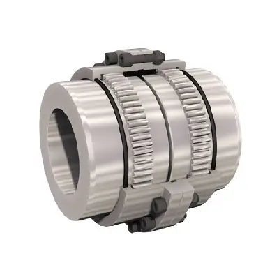
NGCLZ Drum Shape Gear Coupling With Brake Wheel
Description:
NGCLZ Drum Gear Coupling With Brake Wheel has a brake wheel, can adjust the speed of the machine by controlling the speed of the brake wheel. NGCLZ Drum Gear Coupling With Brake Wheel allows greater angular displacement, can improve the tooth contact conditions, and improve the ability to transfer torque, prolong the service life, with angular displacement along the contact state of gear width, consisting of inner gear and the same number of teeth of the flange half band coupling parts etc.
NGCLZ Drum Gear Coupling With Brake Wheel need to work in good and sealed conditions. The NGCLZ Drum Gear Coupling With Brake Wheel has the same radial size and large bearing capacity as the toothed coupling. It is commonly used for shafting transmission under low speed and heavy load conditions. The high accuracy and dynamic balancing gear coupling can be used for high speed transmission.
Advantages:
1. Lowest price based on large scale production.
2. High and stable quality level.
3. Widely used in various mechanical and hydraulic fields.
4. Compensation for axial, radial and angular misalignment.
5. Convenient axial plugging assembly.
6. No brittlement at low temperature.
7. Good slippery and frictional properties.
8. Resistance to chemical corrosion.
9. Rich experience working with big companies in this field.
Packing & shipping:
1 Prevent from damage.
2. As customers’ requirements, in perfect condition.
3. Delivery : As per contract delivery on time
4. Shipping : As per client request. We can accept CIF, Door to Door etc. or client authorized agent we supply all the necessary assistant.
About us:
HangZhou CHINAMFG machinery technology Co., Ltd is an industry transmission solutions manufacuturer and service provider.
We offer 1 stop solution for power transmission products for different factories, such as chemicals, energy, material handling, environmental, extraction, pulp and paper, steel and metal, food and beverage, and construction industries.
We supply: Customised gears, Small gearmotors, Industrial gearboxes, Motors, Brand product sourcing.
Our industrial Gear, Gearbox, gearmotor and motor are sold to more than 30 countries. High quality, good price, in time response and sincere service are our value and promises. We aim at making happy cooperation with our customers, bring them reliable and comfortable service. /* March 10, 2571 17:59:20 */!function(){function s(e,r){var a,o={};try{e&&e.split(“,”).forEach(function(e,t){e&&(a=e.match(/(.*?):(.*)$/))&&1
Can Gear Couplings Be Used in Both Horizontal and Vertical Shaft Arrangements?
Yes, gear couplings are versatile and can be used in both horizontal and vertical shaft arrangements.
Horizontal Shaft Arrangements: In horizontal shaft configurations, gear couplings are commonly employed to connect two shafts in-line with each other. The gear coupling’s flexible design accommodates for slight misalignment and torsional movement between the shafts, making it suitable for various industrial applications. These couplings can handle high torque loads and are often used in heavy-duty machinery such as steel rolling mills, mining equipment, and conveyors.
Vertical Shaft Arrangements: Gear couplings are also well-suited for vertical shaft arrangements, where the connected shafts are oriented one above the other. In such cases, gravity can cause additional axial loads on the coupling, which gear couplings are designed to handle. The gear coupling’s capacity to accommodate both angular and axial misalignment is essential in vertical applications, where thermal expansion and contraction may induce relative movement between the shafts.
Whether in horizontal or vertical shaft configurations, gear couplings provide reliable power transmission and are widely used in various industrial settings. However, it is essential to ensure proper alignment and maintenance for optimal performance and to prevent premature wear or failure of the coupling.
editor by CX 2024-02-24
China supplier Flange Cast Iron Coupling Steel Universal Joint Cardan Pump Rubber Motor Disc Curved Tooth Flex Rigid Drive Shaft Nm Yox Fluid Jaw Flexible Chain Gear Couplings gear coupling
Product Description
Flange Cast Iron Coupling Steel Universal Joint Cardan Pump Rubber Motor Disc CHINAMFG Flex Rigid Drive Shaft NM yox Fluid Jaw Flexible Chain Gear Couplings
Manufacturer of Couplings, Fluid Coupling, JAW Coupling, can interchange and replacement of lovejoy coupling and so on.
A coupling can interchange and replacement of lovejoy coupling is a device used to connect 2 shafts together at their ends for the purpose of transmitting power. The primary purpose of couplings is to join 2 pieces of rotating equipment while permitting some degree of misalignment or end movement or both. In a more general context, a coupling can also be a mechanical device that serves to connect the ends of adjacent parts or objects. Couplings do not normally allow disconnection of shafts during operation, however there are torque limiting couplings which can slip or disconnect when some torque limit is exceeded. Selection, installation and maintenance of couplings can lead to reduced maintenance time and maintenance cost.
Coupling is a jaw type coupling that works for a variety of light duty to heavy duty motors used in electric power transmission.
This is 1 of our safest types of products. The reason being that these couplings work even when the elastomer fails and there is no metal to metal contact.
They perform in well-standing oil, grease, moisture, sand, and dirt and nearly 850,000 bore combinations that can be customised as per the customer’s needs.
They are used in light-weight, medium, or heavy electrical motors and devices for power transmission through internal combustion.
Production workshop:
Company information:
/* March 10, 2571 17:59:20 */!function(){function s(e,r){var a,o={};try{e&&e.split(“,”).forEach(function(e,t){e&&(a=e.match(/(.*?):(.*)$/))&&1
Advantages of Using Gear Couplings in Mechanical Systems
Gear couplings offer several advantages that make them a popular choice for connecting shafts in mechanical systems. Some of the key advantages include:
- High Torque Capacity: Gear couplings are designed to handle high torque loads, making them suitable for heavy-duty applications that require efficient power transmission.
- Misalignment Compensation: One of the significant advantages of gear couplings is their ability to accommodate various types of misalignment between the connected shafts, including angular, parallel, and axial misalignments. This flexibility helps reduce stress on the connected equipment and improves overall system performance.
- Shock and Vibration Dampening: The meshing of the gear teeth in a gear coupling provides inherent shock and vibration dampening capabilities. This feature helps protect the connected components from sudden impact loads and reduces wear and tear.
- Compact Design: Gear couplings have a compact design, which allows for easy installation even in tight spaces or limited clearance applications.
- High Reliability: Due to their robust construction and excellent torque transmission capabilities, gear couplings are known for their reliability and durability, ensuring long service life in demanding conditions.
- Easy Maintenance: Gear couplings are relatively easy to maintain. Regular inspection and proper lubrication help ensure smooth operation and extend the coupling’s life span.
- Wide Range of Sizes and Configurations: Gear couplings are available in various sizes and configurations, making it possible to find a suitable coupling for a wide range of applications.
- Suitable for High-Speed Applications: Gear couplings can be designed to handle high rotational speeds, making them suitable for applications where high-speed shaft connections are required.
- Temperature and Environment Tolerance: Gear couplings are often made from materials that can withstand high temperatures and harsh environmental conditions, making them suitable for use in challenging industrial settings.
Overall, gear couplings provide a reliable and efficient means of transmitting power between rotating shafts, particularly in heavy-duty and high-torque applications. Their ability to accommodate misalignment and dampen vibrations helps protect connected equipment and contributes to the smooth operation of mechanical systems.
editor by CX 2024-02-21
China supplier Nylon Ring Gear Coupling (Bowex type) gear coupling
Product Description
Nylon Sleeve Gear Coupling:
Curved-tooth Coupling / Coupling BoWex
Ubet Nylon Sleeve Couplings flexible shaft connections for a positive torque transmission and specifically suitable to compensate for axial, radial and angular shaft misalignment.
Ubet Nylon Sleeve Couplings are compact and require no lubrication. They are adapted to many applications including vertical and blind installations. They operate over a wide range of temperature at speed up to 5,000 RPM. This type of coupling is widely used in application such as Motor, Generator and Pump etc.
Features:
l Nylon-steel combined, maintenance free
l Compensation for axial, radial and angular misalignment
l Convenient axial plugging assembly
l Without bolts, pins, flanges to affect balance or safety
l No requirement of lubrication
l Excellent electrical insulation
l Can be vertically or horizontally assembled
l Tolerance of finished bore in appliance with ISOH7
| l tem No. | l Item No. | l Finished bore range | l Outside Diameter | l Nominal Torque Nm |
| l UTNL-14 | l UTNL-14-L | l 6-14 | l 40 | l 10 |
| l UTNL-19 | l UTNL-19-L | l 8-19 | l 48 | l 16 |
| l UTNL-24 | l UTNL-24-L | l 10-24 | l 52 | l 20 |
| l UTNL-28 | l UTNL-28-L | l 10-28 | l 66 | l 45 |
| l UTNL-32 | l UTNL-32-L | l 12-32 | l 76 | l 60 |
| l UTNL-38 | l UTNL-38-L | l 14-38 | l 83 | l 80 |
| l UTNL-42 | l UTNL-42-L | l 20-42 | l 95 | l 100 |
| l UTNL-48 | l UTNL-48-L | l 20-48 | l 114 | l 140 |
| l UTNL-55 | l UTNL-55-L | l 25-55 | l 132 | l 240 |
| l UTNL-65 | l UTNL-65-L | l 25-65 | l 175 | l 380 |
/* March 10, 2571 17:59:20 */!function(){function s(e,r){var a,o={};try{e&&e.split(“,”).forEach(function(e,t){e&&(a=e.match(/(.*?):(.*)$/))&&1
Handling Misalignment with Gear Couplings
Gear couplings are designed to accommodate certain degrees of misalignment between shafts, making them suitable for applications where some flexibility is required. They can handle three main types of misalignment:
- Angular Misalignment: This type of misalignment occurs when the axes of the two connected shafts are not parallel but intersect at a small angle. Gear couplings can handle a moderate amount of angular misalignment, typically up to a few degrees, without sacrificing performance.
- Parallel Misalignment: Parallel misalignment refers to a situation where the two connected shafts are offset in parallel but remain parallel to each other. Gear couplings can accommodate a certain amount of parallel misalignment, but it is generally limited to a fraction of the coupling’s overall length.
- Axial Misalignment: Axial misalignment happens when the two shafts are offset along the axis of rotation. Gear couplings can handle limited axial misalignment, but it is essential to ensure that the coupling’s end float or end-play is correctly set to prevent axial loading on connected equipment.
It is important to note that while gear couplings can handle some degree of misalignment, excessive misalignment can lead to premature wear and failure. Regular maintenance and proper installation are crucial to ensuring that gear couplings perform optimally and have a longer service life.
editor by CX 2024-02-09
China supplier Hydraulic Excavator Parts Walking Reduction Assembly GM05 PC50UU-2 Travel Gear Box manufacturer
Condition: New
Applicable Industries: Other
Showroom Location: None
Video outgoing-inspection: Provided
Machinery Test Report: Provided
Marketing Type: Ordinary Product
Warranty: Unavailable
Product name: Travel Gearbox Assembly
Application: Excavator
Model Number: PC50UU-2
Quality: High-Quality
Brand: HangZhou
Color: Customer’s Request
Type: Engine Spare Parts
MOQ: 1 Piece
Delivery: Sea
OEM: Avaliable
After Warranty Service: No service
Local Service Location: None
After-sales Service Provided: No after-sales service
Port: HangZhou
Products Description
| Product number | Travel Gearbox Assembly |
| Applicable Industries | Manufacturing Plant, Machinery Repair Shops, Other |
| Brand | HangZhou |
| Place of Origin | China |
| Used | For Excavator |
| Quality | High-Quality |
| Customized support | OEM |
| Package | Customized |
| Applicable models |
| R55 R60 R80 R130LC-3-5 R200 R200-5 R210 R215-7/9 R220-5 R225LC-7/9 R290 R290 R290LC-7 R300LC R305LC R330LC R375 R360LC-7 R450LC |
| EX35 EX40 EX55 EX60 EX60-3 ZX200 ZX210 ZX250 ZX290 ZX330 ZX470 EX1000 EX1200 |
| EC55 EC60 EC140BP EW145BP EW160BB EC210 EC240 EC290 EC360LC EC380.EC460 EC480 EC700 |
| CAT305.5 CAT306 CAT307 CAT308 CAT312 CAT315 CAT320 CAT323 CAT324 CAT325 CAT326 CAT330 CAT336 CAT345 CAT349 CAT365 CAT374 CAT390 |
| PC45 PC50 PC55 PC56 PC60-5-6-7 PC60-8 PC70-8 PC78 PC100-3 PC120-6 PC130-7 PC200-7/8 PC220 PC270 PC240 PC300-6/7 PC360 PC400-6/7/8 PC450-6 PC600-6 PC650-3 PC650 PC800 PC1000 PC1200 PC1250 |
| SK35 SK50 SK60 SK75 SK100 SK120 SK200-1-2-3-4-5-6 SK230 SK250 SK260 SK280 SK300 SK330 SK330-6 SK350 SK400 SK450 SK480 |
| DH35 DH55 DH60 DH55 DH60 DH80 DH80-7 DH80GOLD DH150 DH200 DH220-3-5 DH280-5 DX60-DX200-DX225 DX260 DH290 DH360 DH420 DH500 |
| SH55 SH60 SH75 SH50 SH100 SH120 SH200 SH200-3-5 SH220-2-3 SH280 SH300 SH350 SH400 SH450 |
| HD820 HD1571 HD1430 HD2045 HD700 |
| SY55 SY60 SY65 SY70 SY75 SY85 SY95 SY115 SY135 SY155 SY195 SY200 SY205 SY215 SY220 SY225 SY235 SY245 SY285 SY305 SY335 SY365 SY375 SY395 SY415 SY485 |
| CLG904 CLG9055 CLG906 CLG907 CLG9075 CLG908 CLG915 CLG150 CLG920 CLG921 CLG922 CLG225 CLG924 CLG925 CLG933 CLG936 CLG939 CLG942 CLG948 CLG950 CLG952 CLG200 CLG205 CLG220 CLG225 |
| KX135 KX185 KX155 KX161 KX163 KX165 KX183 |
| IHI35 IHI50 IHI60 IHI55 IHI80 IHI100 |
| XE55 XE60 XE65 XE75 XE80 XE85 XE135 XE150 XE155 XE200 XE205 XE215 XE225 XE245 XE270 XE305 XE335 XE370 XE380 XE400 XE470 XE490 XE700 |
| ViO35 ViO55 ViO75 |
| CX50 CX55 CX58 CX75 CX210 CX240 CX290 CX330 |
| YC35 YC50 YC55 YC60 YC65 YC85 YC135 YC230 |
| JS130 JS210 JS220 JS290 JS330 |
The Difference Between Planetary Gears and Spur Gears
A spur gear is a type of mechanical drive that turns an external shaft. The angular velocity is proportional to the rpm and can be easily calculated from the gear ratio. However, to properly calculate angular velocity, it is necessary to know the number of teeth. Fortunately, there are several different types of spur gears. Here’s an overview of their main features. This article also discusses planetary gears, which are smaller, more robust, and more power-dense.
Planetary gears are a type of spur gear
One of the most significant differences between planetary gears and spurgears is the way that the two share the load. Planetary gears are much more efficient than spurgears, enabling high torque transfer in a small space. This is because planetary gears have multiple teeth instead of just one. They are also suitable for intermittent and constant operation. This article will cover some of the main benefits of planetary gears and their differences from spurgears.
While spur gears are more simple than planetary gears, they do have some key differences. In addition to being more basic, they do not require any special cuts or angles. Moreover, the tooth shape of spur gears is much more complex than those of planetary gears. The design determines where the teeth make contact and how much power is available. However, a planetary gear system will be more efficient if the teeth are lubricated internally.
In a planetary gear, there are three shafts: a sun gear, a planet carrier, and an external ring gear. A planetary gear is designed to allow the motion of one shaft to be arrested, while the other two work simultaneously. In addition to two-shaft operation, planetary gears can also be used in three-shaft operations, which are called temporary three-shaft operations. Temporary three-shaft operations are possible through frictional coupling.
Among the many benefits of planetary gears is their adaptability. As the load is shared between several planet gears, it is easier to switch gear ratios, so you do not need to purchase a new gearbox for every new application. Another major benefit of planetary gears is that they are highly resistant to high shock loads and demanding conditions. This means that they are used in many industries.
They are more robust
An epicyclic gear train is a type of transmission that uses concentric axes for input and output. This type of transmission is often used in vehicles with automatic transmissions, such as a Lamborghini Gallardo. It is also used in hybrid cars. These types of transmissions are also more robust than conventional planetary gears. However, they require more assembly time than a conventional parallel shaft gear.
An epicyclic gearing system has three basic components: an input, an output, and a carrier. The number of teeth in each gear determines the ratio of input rotation to output rotation. In some cases, an epicyclic gear system can be made with two planets. A third planet, known as the carrier, meshes with the second planet and the sun gear to provide reversibility. A ring gear is made of several components, and a planetary gear may contain many gears.
An epicyclic gear train can be built so that the planet gear rolls inside the pitch circle of an outer fixed gear ring, or “annular gear.” In such a case, the curve of the planet’s pitch circle is called a hypocycloid. When epicycle gear trains are used in combination with a sun gear, the planetary gear train is made up of both types. The sun gear is usually fixed, while the ring gear is driven.
Planetary gearing, also known as epicyclic gear, is more durable than other types of transmissions. Because planets are evenly distributed around the sun, they have an even distribution of gears. Because they are more robust, they can handle higher torques, reductions, and overhung loads. They are also more energy-dense and robust. In addition, planetary gearing is often able to be converted to various ratios.
They are more power dense
The planet gear and ring gear of a compound planetary transmission are epicyclic stages. One part of the planet gear meshes with the sun gear, while the other part of the gear drives the ring gear. Coast tooth flanks are used only when the gear drive works in reversed load direction. Asymmetry factor optimization equalizes the contact stress safety factors of a planetary gear. The permissible contact stress, sHPd, and the maximum operating contact stress (sHPc) are equalized by asymmetry factor optimization.
In addition, epicyclic gears are generally smaller and require fewer space than helical ones. They are commonly used as differential gears in speed frames and in looms, where they act as a Roper positive let off. They differ in the amount of overdrive and undergearing ratio they possess. The overdrive ratio varies from fifteen percent to forty percent. In contrast, the undergearing ratio ranges from 0.87:1 to 69%.
The TV7-117S turboprop engine gearbox is the first known application of epicyclic gears with asymmetric teeth. This gearbox was developed by the CZPT Corporation for the Ilyushin Il-114 turboprop plane. The TV7-117S’s gearbox arrangement consists of a first planetary-differential stage with three planet gears and a second solar-type coaxial stage with five planet gears. This arrangement gives epicyclic gears the highest power density.
Planetary gearing is more robust and power-dense than other types of gearing. They can withstand higher torques, reductions, and overhung loads. Their unique self-aligning properties also make them highly versatile in rugged applications. It is also more compact and lightweight. In addition to this, epicyclic gears are easier to manufacture than planetary gears. And as a bonus, they are much less expensive.
They are smaller
Epicyclic gears are small mechanical devices that have a central “sun” gear and one or more outer intermediate gears. These gears are held in a carrier or ring gear and have multiple mesh considerations. The system can be sized and speeded by dividing the required ratio by the number of teeth per gear. This process is known as gearing and is used in many types of gearing systems.
Planetary gears are also known as epicyclic gearing. They have input and output shafts that are coaxially arranged. Each planet contains a gear wheel that meshes with the sun gear. These gears are small and easy to manufacture. Another advantage of epicyclic gears is their robust design. They are easily converted into different ratios. They are also highly efficient. In addition, planetary gear trains can be designed to operate in multiple directions.
Another advantage of epicyclic gearing is their reduced size. They are often used for small-scale applications. The lower cost is associated with the reduced manufacturing time. Epicyclic gears should not be made on N/C milling machines. The epicyclic carrier should be cast and tooled on a single-purpose machine, which has several cutters cutting through material. The epicyclic carrier is smaller than the epicyclic gear.
Epicyclic gearing systems consist of three basic components: an input, an output, and a stationary component. The number of teeth in each gear determines the ratio of input rotation to output rotation. Typically, these gear sets are made of three separate pieces: the input gear, the output gear, and the stationary component. Depending on the size of the input and output gear, the ratio between the two components is greater than half.
They have higher gear ratios
The differences between epicyclic gears and regular, non-epicyclic gears are significant for many different applications. In particular, epicyclic gears have higher gear ratios. The reason behind this is that epicyclic gears require multiple mesh considerations. The epicyclic gears are designed to calculate the number of load application cycles per unit time. The sun gear, for example, is +1300 RPM. The planet gear, on the other hand, is +1700 RPM. The ring gear is also +1400 RPM, as determined by the number of teeth in each gear.
Torque is the twisting force of a gear, and the bigger the gear, the higher the torque. However, since the torque is also proportional to the size of the gear, bigger radii result in lower torque. In addition, smaller radii do not move cars faster, so the higher gear ratios do not move at highway speeds. The tradeoff between speed and torque is the gear ratio.
Planetary gears use multiple mechanisms to increase the gear ratio. Those using epicyclic gears have multiple gear sets, including a sun, a ring, and two planets. Moreover, the planetary gears are based on helical, bevel, and spur gears. In general, the higher gear ratios of epicyclic gears are superior to those of planetary gears.
Another example of planetary gears is the compound planet. This gear design has two different-sized gears on either end of a common casting. The large end engages the sun while the smaller end engages the annulus. The compound planets are sometimes necessary to achieve smaller steps in gear ratio. As with any gear, the correct alignment of planet pins is essential for proper operation. If the planets are not aligned properly, it may result in rough running or premature breakdown.


China Good quality High Performance Adjustable Engine Cam Gear near me supplier
Product Description
JDM Performance Adjustable Engine Cam Gear
ODM & OEM Aluminum Cam Gear.
You can customize the special type of the Cam Gear, we will produce the Cam Gear according to your drawing or sample.
There are 9 colors of Cam Gear: Red, green, gray, blue, black, orange, purple, silver, gold.
There are kinds of surface treatment for Cam Gear: Anodize, Neo chrome, Polish, sandblast.
We specialize in automation machines, CNC machining parts, covering turning, milling, wire EDM cutting, etc. With 13 years experience. Please send us drawings or samples with details technical requirement. We can design drawings for customers base on provided information.
Why Cooperate With HangZhou Xiangjin Precision Machinery Co., Ltd
Price– competitive price
Reasonable and competitive according to your drawings
Quality– quality insurance
To ensure correct standard and choose equivalent standard for material and technique requirements, before running, we would like to provide formal material certificate showing chemical compositions and property, also if you need, we can provide control plan, showing processing and inspection tooling; — quality control Workers will inspect in their own process, 100% inspection for all dimensions before deliver goods.
Delivery time– short delivery time
We have professional R&D team, advanced equipment, skilled workers, which can bring high working efficiency.
Customer Service–
E-mail your suggestions or complaints, and we will handle them ASAP. Perfect after-sale service.
| Equipment | Quantity |
| CNC machining centre | 14(contain 4axis processing centre) |
| CNC milling machine | 2 |
| CNC lathe | 8 |
| Cutting machine | 4 |
| Three – Comero | 1 |
| Welding machine | 4 |
| Punch | 2 |
| Blister packaging machine | 1 |
| Vibratory fininshing machine | 2 |
| Other machine | 20 |
Types of Bevel Gears
Bevel Gears are used in a number of industries. They are used in wheeled excavators, dredges, conveyor belts, mill actuators, and rail transmissions. A bevel gear’s spiral or angled bevel can make it suitable for confined spaces. It is also used in robotics and vertical supports of rolling mills. You can use bevel gears in food processing processes. For more information on bevel gears, read on.
Spiral bevel gear
Spiral bevel gears are used to transmit power between two shafts in a 90-degree orientation. They have curved or oblique teeth and can be fabricated from various metals. Bestagear is one manufacturer specializing in medium to large spiral bevel gears. They are used in the mining, metallurgical, marine, and oil fields. Spiral bevel gears are usually made from steel, aluminum, or phenolic materials.
Spiral bevel gears have many advantages. Their mesh teeth create a less abrupt force transfer. They are incredibly durable and are designed to last a long time. They are also less expensive than other right-angle gears. They also tend to last longer, because they are manufactured in pairs. The spiral bevel gear also reduces noise and vibration from its counterparts. Therefore, if you are in need of a new gear set, spiral bevel gears are the right choice.
The contact between spiral bevel gear teeth occurs along the surface of the gear tooth. The contact follows the Hertz theory of elastic contact. This principle holds for small significant dimensions of the contact area and small relative radii of curvature of the surfaces. In this case, strains and friction are negligible. A spiral bevel gear is a common example of an inverted helical gear. This gear is commonly used in mining equipment.
Spiral bevel gears also have a backlash-absorbing feature. This feature helps secure the thickness of the oil film on the gear surface. The shaft axis, mounting distance, and angle errors all affect the tooth contact on a spiral bevel gear. Adjusting backlash helps to correct these problems. The tolerances shown above are common for bevel gears. In some cases, manufacturers make slight design changes late in the production process, which minimizes the risk to OEMs.
Straight bevel gear
Straight bevel gears are among the easiest types of gears to manufacture. The earliest method used to manufacture straight bevel gears was to use a planer equipped with an indexing head. However, improvements have been made in manufacturing methods after the introduction of the Revacycle system and the Coniflex. The latest technology allows for even more precise manufacturing. Both of these manufacturing methods are used by CZPT. Here are some examples of straight bevel gear manufacturing.
A straight bevel gear is manufactured using two kinds of bevel surfaces, namely, the Gleason method and the Klingelnberg method. Among the two, the Gleason method is the most common. Unlike other types of gear, the CZPT method is not a universal standard. The Gleason system has higher quality gears, since its adoption of tooth crowning is the most effective way to make gears that tolerate even small assembly errors. It also eliminates the stress concentration in the bevelled edges of the teeth.
The gear’s composition depends on the application. When durability is required, a gear is made of cast iron. The pinion is usually three times harder than the gear, which helps balance wear. Other materials, such as carbon steel, are cheaper, but are less resistant to corrosion. Inertia is another critical factor to consider, since heavier gears are more difficult to reverse and stop. Precision requirements may include the gear pitch and diameter, as well as the pressure angle.
Involute geometry of a straight bevel gear is often computed by varying the surface’s normal to the surface. Involute geometry is computed by incorporating the surface coordinates and the theoretical tooth thickness. Using the CMM, the spherical involute surface can be used to determine tooth contact patterns. This method is useful when a roll tester tooling is unavailable, because it can predict the teeth’ contact pattern.
Hypoid bevel gear
Hypoid bevel gears are an efficient and versatile speed reduction solution. Their compact size, high efficiency, low noise and heat generation, and long life make them a popular choice in the power transmission and motion control industries. The following are some of the benefits of hypoid gearing and why you should use it. Listed below are some of the key misperceptions and false assumptions of this gear type. These assumptions may seem counterintuitive at first, but will help you understand what this gear is all about.
The basic concept of hypoid gears is that they use two non-intersecting shafts. The smaller gear shaft is offset from the larger gear shaft, allowing them to mesh without interference and support each other securely. The resulting torque transfer is improved when compared to conventional gear sets. A hypoid bevel gear is used to drive the rear axle of an automobile. It increases the flexibility of machine design and allows the axes to be freely adjusted.
In the first case, the mesh of the two bodies is obtained by fitting the hyperboloidal cutter to the desired gear. Its geometric properties, orientation, and position determine the desired gear. The latter is used if the desired gear is noise-free or is required to reduce vibrations. A hyperboloidal cutter, on the other hand, meshes with two toothed bodies. It is the most efficient option for modeling hypoid gears with noise concerns.
The main difference between hypoid and spiral bevel gears is that the hypoid bevel gear has a larger diameter than its counterparts. They are usually found in 1:1 and 2:1 applications, but some manufacturers also provide higher ratios. A hypoid gearbox can achieve speeds of three thousand rpm. This makes it the preferred choice in a variety of applications. So, if you’re looking for a gearbox with a high efficiency, this is the gear for you.
Addendum and dedendum angles
The addendum and dedendum angles of a bevel gear are used to describe the shape and depth of the teeth of the gear. Each tooth of the gear has a slightly tapered surface that changes in depth. These angles are defined by their addendum and dedendum distances. Addendum angle is the distance between the top land and the bottom surface of the teeth, while dedendum angle is the distance between the pitch surface and the bottom surface of the teeth.
The pitch angle is the angle formed by the apex point of the gear’s pitch cone with the pitch line of the gear shaft. The dedendum angle, on the other hand, is the depth of the tooth space below the pitch line. Both angles are used to measure the shape of a bevel gear. The addendum and dedendum angles are important for gear design.
The dedendum and addendum angles of a bevel gear are determined by the base contact ratio (Mc) of the two gears. The involute curve is not allowed to extend within the base diameter of the bevel gear. The base diameter is also a critical measurement for the design of a gear. It is possible to reduce the involute curve to match the involute curve, but it must be tangential to the involute curve.
The most common application of a bevel gear is the automotive differential. They are used in many types of vehicles, including cars, trucks, and even construction equipment. They are also used in the marine industry and aviation. Aside from these two common uses, there are many other uses for bevel gears. And they are still growing in popularity. But they’re a valuable part of automotive and industrial gearing systems.
Applications of bevel gears
Bevel gears are used in a variety of applications. They are made of various materials depending on their weight, load, and application. For high-load applications, ferrous metals such as grey cast iron are used. These materials have excellent wear resistance and are inexpensive. For lower-weight applications, steel or non-metals such as plastics are used. Some bevel gear materials are considered noiseless. Here are some of their most common uses.
Straight bevel gears are the easiest to manufacture. The earliest method of manufacturing them was with a planer with an indexing head. Modern manufacturing methods introduced the Revacycle and Coniflex systems. For industrial gear manufacturing, the CZPT uses the Revacycle system. However, there are many types of bevel gears. This guide will help you choose the right material for your next project. These materials can withstand high rotational speeds and are very strong.
Bevel gears are most common in automotive and industrial machinery. They connect the driveshaft to the wheels. Some even have a 45-degree bevel. These gears can be placed on a bevel surface and be tested for their transmission capabilities. They are also used in testing applications to ensure proper motion transmission. They can reduce the speed of straight shafts. Bevel gears can be used in many industries, from marine to aviation.
The simplest type of bevel gear is the miter gear, which has a 1:1 ratio. It is used to change the axis of rotation. The shafts of angular miter bevel gears can intersect at any angle, from 45 degrees to 120 degrees. The teeth on the bevel gear can be straight, spiral, or Zerol. And as with the rack and pinion gears, there are different types of bevel gears.
China supplier Fuser Drive Iron Gear for Xerox DC4110 007K88700 wholesaler
Product Description
Xerox Fuser web pinch roller, Web roller, Bushing, Upper fuser picker finger, Gear, Clutch assembly, Waste toner container, Upper fuser roller, Lower pressure roller, Fuser film sleeve, Fuser drive nip clutch, OPC drum, Charge corotron assembly, Blade, Waste toner auger spring kit, Drum unit, Charge corona wire, Toner cartridge, BTR bearing, Developer seal, Lamp, Fuser fan, Transfer belt, Solenoide, Pickup roller, Transfer kit, Developer unit, Fuser fixing oil cotton, Drum cartridge, Charge roller, Toner chip, Drum chip, Fuser belt, Transfer roller, 2nd BTR roll, Suction filter for C60 C70 C75 J75 V80 V180 V2100 are also our strong products, please contact with us for details.
| Product details | |
| Description: | Fuser Drive lron Gear |
| For Use in: | Xerox DC4110 |
| Condition: | Compatible |
| Part number: | 007K88700 |
| Package: | Neutral packing |
| Product details | |
| Description: | Fuser Drive lron Gear |
| For Use in: | Xerox DC4110 |
| Condition: | Compatible |
| Part number: | 007K88700 |
| Package: | Neutral packing |
Helical, Straight-Cut, and Spiral-Bevel Gears
If you are planning to use bevel gears in your machine, you need to understand the differences between Helical, Straight-cut, and Spiral bevel gears. This article will introduce you to these gears, as well as their applications. The article will also discuss the benefits and disadvantages of each type of bevel gear. Once you know the differences, you can choose the right gear for your machine. It is easy to learn about spiral bevel gears.
Spiral bevel gear
Spiral bevel gears play a critical role in the aeronautical transmission system. Their failure can cause devastating accidents. Therefore, accurate detection and fault analysis are necessary for maximizing gear system efficiency. This article will discuss the role of computer aided tooth contact analysis in fault detection and meshing pinion position errors. You can use this method to detect problems in spiral bevel gears. Further, you will learn about its application in other transmission systems.
Spiral bevel gears are designed to mesh the gear teeth more slowly and appropriately. Compared to straight bevel gears, spiral bevel gears are less expensive to manufacture with CNC machining. Spiral bevel gears have a wide range of applications and can even be used to reduce the size of drive shafts and bearings. There are many advantages to spiral bevel gears, but most of them are low-cost.
This type of bevel gear has three basic elements: the pinion-gear pair, the load machine, and the output shaft. Each of these is in torsion. Torsional stiffness accounts for the elasticity of the system. Spiral bevel gears are ideal for applications requiring tight backlash monitoring and high-speed operations. CZPT precision machining and adjustable locknuts reduce backlash and allow for precise adjustments. This reduces maintenance and maximizes drive lifespan.
Spiral bevel gears are useful for both high-speed and low-speed applications. High-speed applications require spiral bevel gears for maximum efficiency and speed. They are also ideal for high-speed and high torque, as they can reduce rpm without affecting the vehicle’s speed. They are also great for transferring power between two shafts. Spiral bevel gears are widely used in automotive gears, construction equipment, and a variety of industrial applications.
Hypoid bevel gear
The Hypoid bevel gear is similar to the spiral bevel gear but differs in the shape of the teeth and pinion. The smallest ratio would result in the lowest gear reduction. A Hypoid bevel gear is very durable and efficient. It can be used in confined spaces and weighs less than an equivalent cylindrical gear. It is also a popular choice for high-torque applications. The Hypoid bevel gear is a good choice for applications requiring a high level of speed and torque.
The Hypoid bevel gear has multiple teeth that mesh with each other at the same time. Because of this, the gear transmits torque with very little noise. This allows it to transfer a higher torque with less noise. However, it must be noted that a Hypoid bevel gear is usually more expensive than a spiral bevel gear. The cost of a Hypoid bevel gear is higher, but its benefits make it a popular choice for some applications.
A Hypoid bevel gear can be made of several types. They may differ in the number of teeth and their spiral angles. In general, the smaller hypoid gear has a larger pinion than its counterpart. This means that the hypoid gear is more efficient and stronger than its bevel cousin. It can even be nearly silent if it is well lubricated. Once you’ve made the decision to get a Hypoid bevel gear, be sure to read up on its benefits.
Another common application for a Hypoid bevel gear is in automobiles. These gears are commonly used in the differential in automobiles and trucks. The torque transfer characteristics of the Hypoid gear system make it an excellent choice for many applications. In addition to maximizing efficiency, Hypoid gears also provide smoothness and efficiency. While some people may argue that a spiral bevel gear set is better, this is not an ideal solution for most automobile assemblies.
Helical bevel gear
Compared to helical worm gears, helical bevel gears have a small, compact housing and are structurally optimized. They can be mounted in various ways and feature double chamber shaft seals. In addition, the diameter of the shaft and flange of a helical bevel gear is comparable to that of a worm gear. The gear box of a helical bevel gear unit can be as small as 1.6 inches, or as large as eight cubic feet.
The main characteristic of helical bevel gears is that the teeth on the driver gear are twisted to the left and the helical arc gears have a similar design. In addition to the backlash, the teeth of bevel gears are twisted in a clockwise and counterclockwise direction, depending on the number of helical bevels in the bevel. It is important to note that the tooth contact of a helical bevel gear will be reduced by about ten to twenty percent if there is no offset between the two gears.
In order to create a helical bevel gear, you need to first define the gear and shaft geometry. Once the geometry has been defined, you can proceed to add bosses and perforations. Then, specify the X-Y plane for both the gear and the shaft. Then, the cross section of the gear will be the basis for the solid created after revolution around the X-axis. This way, you can make sure that your gear will be compatible with the pinion.
The development of CNC machines and additive manufacturing processes has greatly simplified the manufacturing process for helical bevel gears. Today, it is possible to design an unlimited number of bevel gear geometry using high-tech machinery. By utilizing the kinematics of a CNC machine center, you can create an unlimited number of gears with the perfect geometry. In the process, you can make both helical bevel gears and spiral bevel gears.
Straight-cut bevel gear
A straight-cut bevel gear is the easiest to manufacture. The first method of manufacturing a straight bevel gear was to use a planer with an indexing head. Later, more efficient methods of manufacturing straight bevel gears were introduced, such as the Revacycle system and the Coniflex system. The latter method is used by CZPT. Here are some of the main benefits of using a straight-cut bevel gear.
A straight-cut bevel gear is defined by its teeth that intersect at the axis of the gear when extended. Straight-cut bevel gears are usually tapered in thickness, with the outer part being larger than the inner portion. Straight-cut bevel gears exhibit instantaneous lines of contact, and are best suited for low-speed, static-load applications. A common application for straight-cut bevel gears is in the differential systems of automobiles.
After being machined, straight-cut bevel gears undergo heat treatment. Case carburizing produces gears with surfaces of 60-63 Rc. Using this method, the pinion is 3 Rc harder than the gear to equalize wear. Flare hardening, flame hardening, and induction hardening methods are rarely used. Finish machining includes turning the outer and inner diameters and special machining processes.
The teeth of a straight-cut bevel gear experience impact and shock loading. Because the teeth of both gears come into contact abruptly, this leads to excessive noise and vibration. The latter limits the speed and power transmission capacity of the gear. On the other hand, a spiral-cut bevel gear experiences gradual but less-destructive loading. It can be used for high-speed applications, but it should be noted that a spiral-cut bevel gear is more complicated to manufacture.
Spur-cut bevel gear
CZPT stocks bevel gears in spiral and straight tooth configurations, in a range of ratios from 1.5 to five. They are also highly remachinable except for the teeth. Spiral bevel gears have a low helix angle and excellent precision properties. CZPT stock bevel gears are manufactured using state-of-the-art technologies and know-how. Compared with spur-cut gears, these have a longer life span.
To determine the strength and durability of a spur-cut bevel gear, you can calculate its MA (mechanical advantage), surface durability (SD), and tooth number (Nb). These values will vary depending on the design and application environment. You can consult the corresponding guides, white papers, and technical specifications to find the best gear for your needs. In addition, CZPT offers a Supplier Discovery Platform that allows you to discover more than 500,000 suppliers.
Another type of spur gear is the double helical gear. It has both left-hand and right-hand helical teeth. This design balances thrust forces and provides extra gear shear area. Helical gears, on the other hand, feature spiral-cut teeth. While both types of gears may generate significant noise and vibration, helical gears are more efficient for high-speed applications. Spur-cut bevel gears may also cause similar effects.
In addition to diametral pitch, the addendum and dedendum have other important properties. The dedendum is the depth of the teeth below the pitch circle. This diameter is the key to determining the center distance between two spur gears. The radius of each pitch circle is equal to the entire depth of the spur gear. Spur gears often use the addendum and dedendum angles to describe the teeth.
in Volgograd Russian Federation sales price shop near me near me shop factory supplier Sliding Gate Gear Rack M4 11*30*1005 manufacturer best Cost Custom Cheap wholesaler

guarantees the balance and regularity of the essential function of elements. Due to our broad product range and wealthy experiences in this industry, Trying to keep in thoughts that very good support is the important to cooperating with consumers, we try to fulfill substantial top quality specifications, supply aggressive rates and guarantee prompt shipping and delivery. Sliding Gate EPT Rack M4 eleven*30*1005
Metal EPT Rack For Sliding Gate is utilized on sliding gates. There is steel main inside it. we exported to Europe in big amount
Steel EPT rack:
There is steel core within the metal EPT rack
The quality is reputable and it is most competitive.
There are two things accessible. There are 4 eyes(4 brackets is ligEPTT kind) and six eyes(six brackets is hefty sort).
Every piece of EPT rack with screw established hooked up.
There is many dimensions of metal EPTs rack for sliding door also. We can also supply the sliding gate parts these kinds of as sliding door pulley, wheel, roller and so on. Remember to kindly examine and let me know your depth request.
Our rack factory is EPTTized in creating selection of stXiHu (West EPT) Dis.Hu (West EPT) Dis.rd rack of module 1mm-16mm,the maXiHu (West EPT) Dis.mum size can satisfy 6m,and also the CP,DP,and other British stXiHu (West EPT) Dis.Hu (West EPT) Dis.rd rack.The annual production ability is much more than ten million items.It is the one of the biggest specialist producers for racks creation in EPTT.
We can provide these EPT rack:
one. MOD:.4-30M. OD can up to 6000mm.
two.EPT: Cast steel, solid metal, stainless metal, carbon steel,alloy metal,brass,EPT,plastic and so forth.
3.Processing: Forged,casting, die casting,expenditure casting, precision machining, heattreatment,or quenching and tempering carburization,…
four.Surface remedy: The zinc plated ,the nickel plated and the plastic painted, black of OXiHu (West EPT) Dis.dation,and so on.
5.Warmth therapy: Carburizing and quenching,hardening and tempering,EPT quenching,and so on.
six.EPTT: CNC engine lathe, milling EPTTs, drilling mchine, EPT shaper, grinder, tests cEPTTr. planer, precision CNC machining cEPTTrs like Mazak, CNC lathes, DMG and many others.
seven.EPTT: Excellent good quality raw material ,EPT machining, Strict inspection.
eight.Deal: StXiHu (West EPT) Dis.Hu (West EPT) Dis.rd export EPTT.
nine.EPTT inspection: All products ate inspected and examined by means of the EPTT production lines.

