Tag Archives: china couplings

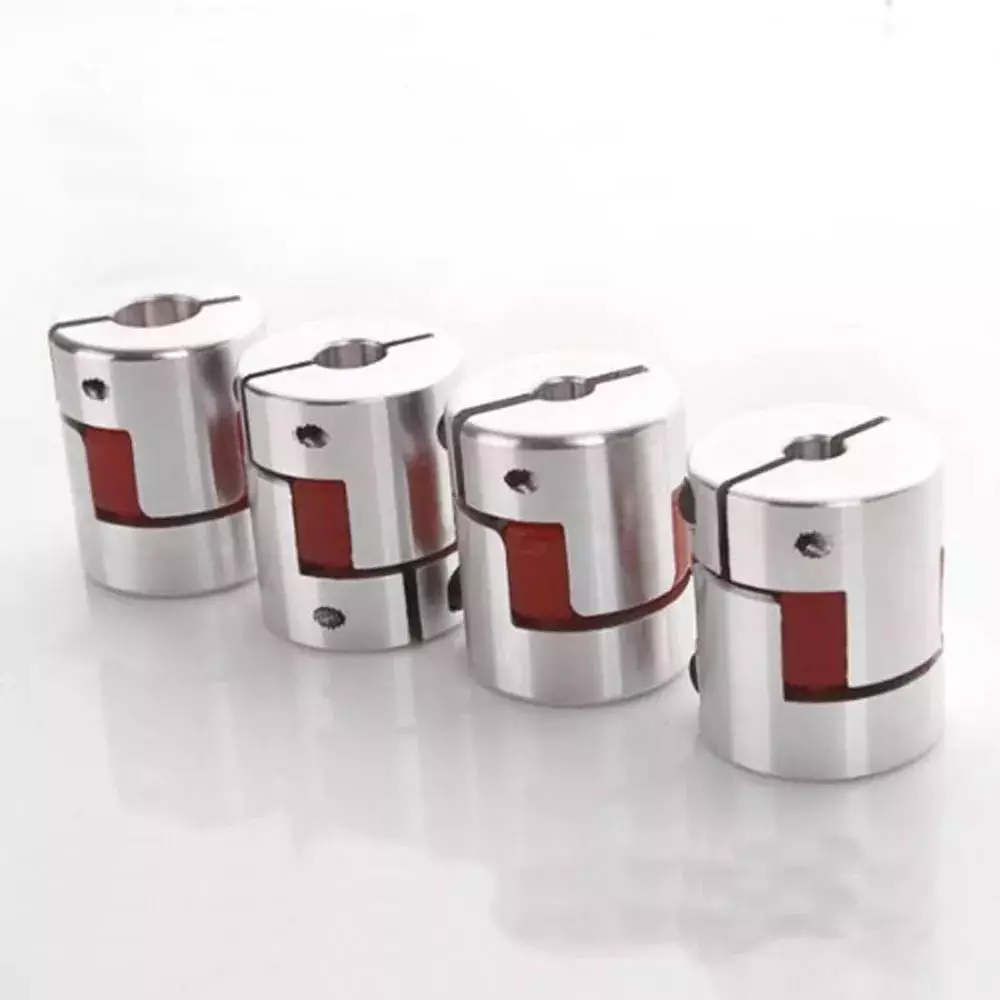
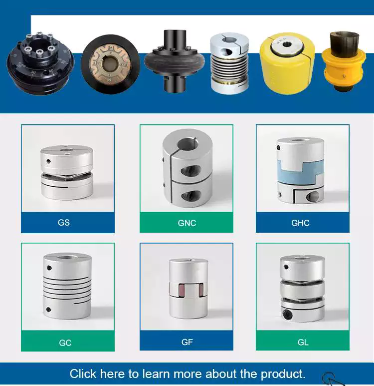
China Servo Motor High Torque Clamping Type Single Disk Flexible Couplings coupling define

Item Description

Product No. φD L W L1 M Tighten the strength(N.m)
SG7-8-C19- 19.5 20 one.two 9.4 M2.5 1
SG7-8-C26- 26 25.5 two.5 11.5 M3 1.5
SG7-8-C34- 34 32.3 three.3 14.five M4 1.five
SG7-8-C39- 39 34.one four.1 15 M4 2.5
SG7-8-C44- 44 34.5 4.five 15 M4 two.five
SG7-8-C50- 50 40.5 four.5 eighteen M5 seven
SG7-8-C56- 56 45 5 20 M5 7
SG7-8-C68- 68 54 6 24 M6 12
SG7-8-C82- eighty two 68 8 thirty M8 16
SG7-8-C94- 94 68 eight thirty M8 28
SG7-8-C104- 104 70 10 thirty M8 28

Item No. Rated torque Highest Torque Max Velocity Inertia Moment N.m rad RRO Tilting Tolerance End-perform Weight:(g)
SG7-8-C19- 1N.m 2N.m 10000prm .65×10-6kg.m² 200N.m/rad .04mm 1c ±0.2mm 12
SG7-8-C26- 1.4N.m 2.8N.m 10000prm one.8×10-6kg.m² 690N.m/rad .04mm 1c ±0.2mm 31
SG7-8-C34- two.8N.m five.6N.m 10000prm 7.2×10⁻⁶kg.m² 1650N.m/rad .04mm 1c ±0.2mm 64
SG7-8-C39- 5.8N.m eleven.6N.m 10000prm one.8×10-5kg.m² 2500N.m/rad .04mm 1c ±0.2mm 97
SG7-8-C44- eight.7N.m 17.4N.m 10000prm two.5×10-5kg.m² 2900N.m/rad .04mm 1c ±0.2mm 113
SG7-8-C50- 15N.m 30N.m 10000prm eight.2×10-5kg.m² 6700N.m/rad .04mm 1c ±0.2mm 195
SG7-8-C56- 25N.m 50N.m 10000prm 1×10⁻⁴kg.m² 8400N.m/rad .04mm 1c ±0.2mm 263
SG7-8-C68- 55N.m 110N.m 10000prm 1.9×10⁻⁴kg.m² 11500N.m/rad .04mm 1c ±0.2mm 445
SG7-8-C82- 80N.m 160N.m 10000prm 7×10⁻⁴kg.m² 14550N.m/rad .04mm 1c ±0.2mm 892
SG7-8-C94- 185N.m 370N.m 10000prm 1.23×10⁻³kg.m² 16900N.m/rad .04mm 1c ±0.2mm 950
SG7-8-C104- 255N.m 510N.m 10000prm one.86×10-3kg.m² 25100N.m/rad .04mm 1c ±0.2mm 1190

US $12-32
/ Piece
|
1 Piece

(Min. Order)

###

Standard Or Nonstandard: Nonstandard
Shaft Hole: Customized
Torque: 2-250n.M
Bore Diameter: Customized
Speed: 10000r/M
Structure: Flexible

###

Item No. φD L W L1 M Tighten the strength(N.m)
SG7-8-C19- 19.5 20 1.2 9.4 M2.5 1
SG7-8-C26- 26 25.5 2.5 11.5 M3 1.5
SG7-8-C34- 34 32.3 3.3 14.5 M4 1.5
SG7-8-C39- 39 34.1 4.1 15 M4 2.5
SG7-8-C44- 44 34.5 4.5 15 M4 2.5
SG7-8-C50- 50 40.5 4.5 18 M5 7
SG7-8-C56- 56 45 5 20 M5 7
SG7-8-C68- 68 54 6 24 M6 12
SG7-8-C82- 82 68 8 30 M8 16
SG7-8-C94- 94 68 8 30 M8 28
SG7-8-C104- 104 70 10 30 M8 28

###

Item No. Rated torque Maximum Torque Max Speed Inertia Moment N.m rad RRO Tilting Tolerance End-play Weight:(g)
SG7-8-C19- 1N.m 2N.m 10000prm 0.65×10⁻⁶kg.m² 200N.m/rad 0.04mm 1c ±0.2mm 12
SG7-8-C26- 1.4N.m 2.8N.m 10000prm 1.8×10⁻⁶kg.m² 690N.m/rad 0.04mm 1c ±0.2mm 31
SG7-8-C34- 2.8N.m 5.6N.m 10000prm 7.2×10⁻⁶kg.m² 1650N.m/rad 0.04mm 1c ±0.2mm 64
SG7-8-C39- 5.8N.m 11.6N.m 10000prm 1.8×10⁻⁵kg.m² 2500N.m/rad 0.04mm 1c ±0.2mm 97
SG7-8-C44- 8.7N.m 17.4N.m 10000prm 2.5×10⁻⁵kg.m² 2900N.m/rad 0.04mm 1c ±0.2mm 113
SG7-8-C50- 15N.m 30N.m 10000prm 8.2×10⁻⁵kg.m² 6700N.m/rad 0.04mm 1c ±0.2mm 195
SG7-8-C56- 25N.m 50N.m 10000prm 1×10⁻⁴kg.m² 8400N.m/rad 0.04mm 1c ±0.2mm 263
SG7-8-C68- 55N.m 110N.m 10000prm 1.9×10⁻⁴kg.m² 11500N.m/rad 0.04mm 1c ±0.2mm 445
SG7-8-C82- 80N.m 160N.m 10000prm 7×10⁻⁴kg.m² 14550N.m/rad 0.04mm 1c ±0.2mm 892
SG7-8-C94- 185N.m 370N.m 10000prm 1.23×10⁻³kg.m² 16900N.m/rad 0.04mm 1c ±0.2mm 950
SG7-8-C104- 255N.m 510N.m 10000prm 1.86×10⁻³kg.m² 25100N.m/rad 0.04mm 1c ±0.2mm 1190

What Is a Coupling?

A coupling is a device that connects two shafts together. It transmits power from one to the other and is used to join rotating equipment. It can also allow for some degree of misalignment and end movement. It is used in mechanical engineering and manufacturing. To learn more about couplings, read this article.
gearboxMechanical connection between two objectsThe present invention relates to a method and assembly for forming a mechanical connection between two objects. The methods of this invention are suitable for connecting both solid and hollow objects. For example, the method can be used to make mechanical connections between two cylinders. This method is particularly useful for connecting two cylinders that are positioned near each other.

Absorbs vibration

A coupling insert is a part of a vehicle’s drivetrain that absorbs vibrations. These inserts are designed to prevent couplings from moving out of phase. However, the coupling inserts themselves can wear out and need to be replaced. Universal joints are an alternative if the coupling is out of phase by more than one degree. In addition, internal bearings in the coupling need to be lubricated and replaced when they begin to show signs of wear.
Another embodiment of the invention includes a flexible coupling 25 that includes rearwardly-extending lugs that extend toward the coupling member 23. These lugs interdigitate with corresponding lugs on the coupling member 23. They are spaced circumferentially. A first elastic member 28 is interposed between lugs 26 and 27, and is adapted to yield in a counterclockwise direction. As a result, it absorbs torsional vibrations.
gearbox

Blocks heat transfer

Thermal coupling occurs when a solid block is thermally coupled to the air or fluid passing through it. The amount of heat transferred through a solid block depends on the heat transfer coefficients of the materials. This paper presents a numerical model to understand how heat transfers through different block materials. This work also describes the thermal resistance network for a one-dimensional block.
In some cases, thermal coupling increases the heat transfer mechanism. As illustrated in FIG. 1D, a heatpipe coupler 112 couples two heatpipes 110-1 and 110-2. This configuration allows the pipes to be coupled to the heat source and to the condenser. In addition, the heat pipe couplers may have bellows at the ends to help facilitate linear motion.
Thermal coupling is achieved by ensuring that at least one block is made of a material with a lower thermal expansion coefficient than the annulus. Ideally, the block’s mean thermal expansion coefficient is at least twenty percent lower than the annulus’s mean thermal expansion coefficient. This ensures that the thermal coupling between the two parts is as efficient as possible.
Another type of thermal coupling is achieved by using flexible elements. These are often washers or springs. These components allow the blocks to maintain physical contact with the post 55, which means that the heat transfer is more efficient even at higher temperatures. The flexibility of these elements also makes it possible to choose an element that will not impede assembly.
gearbox

Protects rotating equipment

A reliable, long-lasting coupling system can reduce the risk of damage to rotating equipment. Designed to protect against torque overload and wear, Voith torque-limiting couplings provide outstanding safety and reliability. As a result, they can deliver maximum performance and minimize equipment downtime. In addition to their long-term benefits, these solutions are ideal for applications where safety and reliability are of paramount importance.
A good coupling provides many advantages, including the ability to transmit power, compensate for axial movement, and absorb shock. It is essential to choose the proper coupling for your application based on the basic conditions of your rotating equipment. For example, if you have two shafts with parallel rotation axes, you should choose a parallel coupling. Otherwise, you should use an angular coupling.
Torque-limiting couplings can also provide protection for rotating equipment by disengaging at a specific torque level. This protects the drive shaft from undergoing catastrophic failure. Torque limiters are particularly helpful for high-value equipment. By preventing catastrophic failure, you can avoid expensive repairs and minimize equipment downtime.
Coupling guards are easy to install and provide effective protection for rotating equipment. These covers are made of sheet metal bent to fit over the shaft. They are durable and easy to remove when necessary. This type of guard can prevent employees from catching their hands, tools, or loose clothing on motor coupling components.
China Servo Motor High Torque Clamping Type Single Disk Flexible Couplings     coupling defineChina Servo Motor High Torque Clamping Type Single Disk Flexible Couplings     coupling define
editor by czh 2023-01-06

China Chinese Manufacturer Stainless Steel Pipe Fittings Female to Female Hex Couplings coupling beam

Product Description

Hikelok Pipe Fittings- Hex Couplings

Instrumentation Pipe Fittings

Offered in sizes from 1/16 to 2 in. and 6mm to 30mm.

Hikelok pipe fittings materials contain stainless metal, alloy400/R-405, brass and duplex metal.

Hikelok supplies NPT, ISO/BSP, SAE and ISO threads configurations.

Burr-totally free clean thread provide optimum sealing and lessen galling.
 

Materials Expectations

Content Bar inventory Forgings
316 stainless steel

ASTM A276

ASME SA479, EN 1.4401

ASTM A182

ASME SA182, EN 1.4401

Alloy twenty ASTM B473 ASTM B462
Alloy four hundred/R-405

ASTM B164,

ASME SB164

ASTM B564,

ASME SB564

Alloy 600 ASTM B166,ASME SB166 ASTM B564,ASME SB564
Alloy 625 ASTM B446 ASTM B564,ASME SB564
Alloy 825 ASTM B425 ASTM B564,ASME SB564
Alloy C-276 ASTM B574 ASTM B564
Aluminum ASTM B211 ASTM B247
Brass ASTM B16,ASTM ASTM B283
Carbon steel B453 ASTM A108

Thread Specs


Thread Kind(Stop Relationship) Reference Specification
NPT ASME B1.20.1,SAE AS71051

ISO/BSP(parallel)

(Based mostly on DIN 3852)

(Hikelok PPT,BP,and BS fittings)

ISO 228,JIS B5712

ISO/BSP(tapered)

(Based mostly on DIN 3852)

(Hikelok BT fittings)

ISO 7,BS EN 15716-1,

JIS B5713

ISO/BSP(gauge)

(Primarily based on EN 837-1 and 837-3)

(Hikelok BG)

ISO 228

Unified (SAE)

(Hikelok SA fittings)

ASME B1.one

Operating Temperature Rating
 

Materials

Doing work Temperature Score

ºF(ºC)

316 stainless steel -65(-fifty three) to a thousand(537)
Brass -20(-28) to four hundred(204)
Carbon steel -65(-53) to 375(a hundred ninety)
BS gaskets(FKM) -5(-15) to 400(204)
BG BP gaskets(copper) -5(-fifteen) to 400(204)
SAE O-ring (FKM) -5(-fifteen) to 400(204)

NPT Thread Pressure Scores

Rankings are dependent on ASME Code for Pressure Piping B31.3,

Process Piping, at ambient temperature.

NPT/
ISO
Pipe
Dimension
316 S.S. and Carbon Steel Brass
Male Female Male Female
psig bar psig bar psig bar psig bar
1/16 11000 760 6700 460 5500 380 3300 230
1/eight 10000 690 6500 440 5000 340 3200 220
1/four 8000 550 6600 450 4000 270 3300 220
3/8 7800 540 5300 360 3900 270 2600 a hundred and eighty
one/2 7700 530 4900 330 3800 260 2400 160
3/four 7300 five hundred 4600 320 3600 250 2300 one hundred sixty
1 5300 370 4400 three hundred 2600 180 2200 a hundred and fifty
1 1/4 6000 410 5000 350 3000 two hundred 2500 170
1 1/2 5000 340 4600 310 2500 170 2300 a hundred and fifty
2 3900 270 3900 270 1900 130 1900 a hundred thirty


Certifications

Firm Introduction

Manufacturing unit

Our Companies

FAQ


US $2-40
/ Piece
|
1 Piece

(Min. Order)

###

Standard: ANSI, GB, JIS
Material: Stainless Steel
Connection: Female
Head Type: Hexagon
Product Name: Hex Couplings
Body Material: Stainless Steel

###

Samples:
US$ 2/Piece
1 Piece(Min.Order)

|
Request Sample

###

Customization:

###

Material Bar stock Forgings
316 stainless steel
ASTM A276
ASME SA479, EN 1.4401
ASTM A182
ASME SA182, EN 1.4401
Alloy 20 ASTM B473 ASTM B462
Alloy 400/R-405
ASTM B164,
ASME SB164
ASTM B564,
ASME SB564
Alloy 600 ASTM B166,ASME SB166 ASTM B564,ASME SB564
Alloy 625 ASTM B446 ASTM B564,ASME SB564
Alloy 825 ASTM B425 ASTM B564,ASME SB564
Alloy C-276 ASTM B574 ASTM B564
Aluminum ASTM B211 ASTM B247
Brass ASTM B16,ASTM ASTM B283
Carbon steel B453 ASTM A108

###

Thread Type(End Connection) Reference Specification
NPT ASME B1.20.1,SAE AS71051
ISO/BSP(parallel)
(Based on DIN 3852)
(Hikelok PPT,BP,and BS fittings)
ISO 228,JIS B0202
ISO/BSP(tapered)
(Based on DIN 3852)
(Hikelok BT fittings)
ISO 7,BS EN 10226-1,
JIS B0203
ISO/BSP(gauge)
(Based on EN 837-1 and 837-3)
(Hikelok BG)
ISO 228
Unified (SAE)
(Hikelok SA fittings)
ASME B1.1

###

Material
Working Temperature Rating
ºF(ºC)
316 stainless steel -65(-53) to 1000(537)
Brass -20(-28) to 400(204)
Carbon steel -65(-53) to 375(190)
BS gaskets(FKM) -5(-15) to 400(204)
BG BP gaskets(copper) -5(-15) to 400(204)
SAE O-ring (FKM) -5(-15) to 400(204)

###

NPT/
ISO
Pipe
Size
316 S.S. and Carbon Steel Brass
Male Female Male Female
psig bar psig bar psig bar psig bar
1/16 11000 760 6700 460 5500 380 3300 230
1/8 10000 690 6500 440 5000 340 3200 220
1/4 8000 550 6600 450 4000 270 3300 220
3/8 7800 540 5300 360 3900 270 2600 180
1/2 7700 530 4900 330 3800 260 2400 160
3/4 7300 500 4600 320 3600 250 2300 160
1 5300 370 4400 300 2600 180 2200 150
1 1/4 6000 410 5000 350 3000 200 2500 170
1 1/2 5000 340 4600 310 2500 170 2300 150
2 3900 270 3900 270 1900 130 1900 130

Types of Couplings

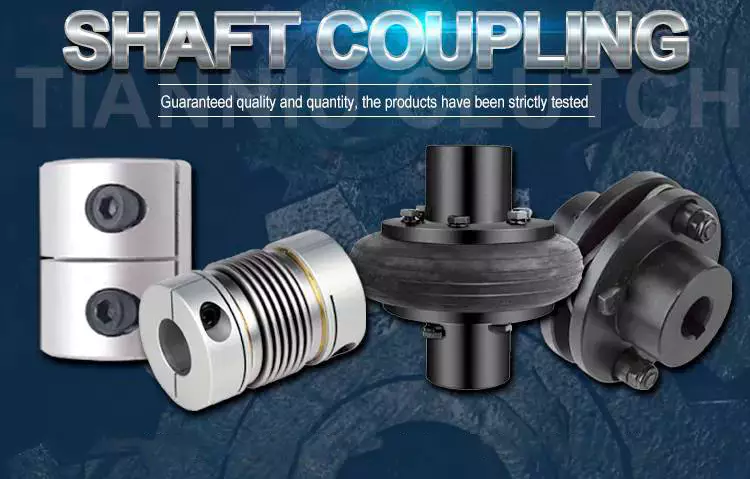
A coupling is a device that connects two shafts and transmits power from one to the other. Its main purpose is to join two pieces of rotating equipment. It also allows for some degree of misalignment or end movement. Here are a few examples of coupling types: Beam coupling, Flexible coupling, Magnetic coupling, and Shaft coupling.
gearbox

Beam coupling

Beam couplings are used to couple motors and other devices. They are available in several types, including flexible, slit, and rigid beam couplings. Each has unique properties and characteristics. These couplings are best for applications requiring a high level of precision and long life. They are also a practical solution for the connection of stepping and servo motors with screw rods.
Beam couplings are usually made of stainless steel or aluminum alloy, and feature spiral and parallel cut designs. Multiple cuts allow the coupling to accommodate multiple beams and improve angular and parallel misalignment tolerances. Additionally, beam couplings are comparatively cheaper than other types of rotary joints, and they require minimal maintenance.
The materials of a beam coupling should be considered early in the specification process. They are typically made of aluminum or stainless steel, but they can also be manufactured from Delrin, titanium, and other engineering grade materials. Beam couplings are often available in multiple sizes to fit specific shaft diameters.
Beam couplings are a key component of motion control systems. They provide excellent characteristics when used properly, and they are a popular choice for many applications. A thorough understanding of each type of coupling will help to prevent coupling failure and enhance system performance. Therefore, it is important to choose the right coupling for your application.
Various types of beam couplings have unique advantages and disadvantages. The FCR/FSR design has two sets of three beams. It is available in both metric and inch shaft sizes. The FCR/FSR couplings are ideal for light-duty power transmission applications. A metric shaft is more suitable for these applications, while an inch shaft is preferred for heavier duty applications.
Two types of beam couplings are available from Ruland. The Ruland Flexible beam coupling has a multi-helical cut design that offers a greater flexibility than commodity beam couplings. This design allows for higher torque capabilities while minimizing wind-up. In addition, it is also more durable than its commodity counterparts.

Flexible coupling

A flexible coupling is a versatile mechanical connection that allows for the easy coupling of two moving parts. The design of these couplings allows for a variety of stiffness levels and can address a variety of problems, such as torsional vibrations or critical speed. However, there are a number of tradeoffs associated with flexible couplings.
One of the biggest issues is the installation of the coupling, which requires stretching. This problem can be exacerbated by cold temperatures. In such a case, it is vital to install the coupling properly. Using a gear clamp is one of the most important steps in a successful installation. A gear clamp will keep the coupling in place and prevent it from leaking.
Another common type of flexible coupling is the gear coupling. These couplings are composed of two hubs with crowned external gear teeth that mesh with two internally splined flanged sleeves. The massive size of the teeth makes them resemble gears. Gear couplings offer good torque characteristics but require periodic lubrication. These couplings can also be expensive and have a limited number of applications.
Another type of flexible coupling is the SDP/SI helical coupling. These couplings can accommodate axial motion, angular misalignment, and parallel offset. This design incorporates a spiral pattern that makes them flexible. These couplings are available in stainless steel and aluminum.
A flexible coupling has a wide range of applications. Generally, it is used to connect two rotating pieces of equipment. Depending on its design, it can be used to join two pieces of machinery that move in different directions. This type of coupling is a type of elastomeric coupling, which has elastic properties.
There are many types of flexible couplings available for different types of applications. The purpose of a flexible coupling is to transmit rotational power from one shaft to another. It is also useful for transmitting torque. However, it is important to note that not all flexible couplings are created equally. Make sure to use a reputable brand for your coupling needs. It will ensure a reliable connection.
The simplest and most commonly used type of flexible coupling is the grid coupling. This type of coupling uses two hubs with slotted surfaces. The steel grid is allowed to slide along these slots, which gives it the ability to flex. The only limitation of this type of coupling is that it can only tolerate a 1/3 degree misalignment. It can transmit torques up to 3,656 Nm.
gearbox

Magnetic coupling

Magnetic coupling is a technique used to transfer torque from one shaft to another using a magnetic field. It is the most common type of coupling used in machinery. It is highly effective when transferring torque from a rotating motor to a rotating shaft. Magnetic couplings can handle high torques and high speeds.
Magnetic coupling is described by the energy difference between a high-spin state and a broken symmetry state, with the former being the energy of a true singlet state. In single-determinant theories, this energy difference is called the Kij. Usually, the broken-symmetry state is a state with two interacting local high-spin centers.
The magnetic coupling device is regarded as a qualitative leap in the reaction still industry. It has solved a number of problems that had plagued the industry, including flammability, explosiveness, and leakage. Magnetic couplings are a great solution for many applications. The chemical and pharmaceutical industries use them for various processes, including reaction stills.
Magnetic couplings are a good choice for harsh environments and for tight spaces. Their enclosed design keeps them fluid and dust-proof. They are also corrosion-resistant. In addition, magnetic couplings are more affordable than mechanical couplings, especially in areas where access is restricted. They are also popular for testing and temporary installations.
Another use for magnetic coupling is in touch screens. While touch screens use capacitive and resistive elements, magnetic coupling has found a cool new application in wireless charging. While the finger tracking on touch screens may seem like a boley job, the process is very sensitive. The devices that use wireless charging need to have very large coils that are locked into resonant magnetic coupling.
Magnetic couplings also help reduce hydraulic horsepower. They cushion starts and reduce alignment problems. They can also improve flow in oversized pumps. A magnetic coupling with an 8 percent air gap can reduce hydraulic HP by approximately 27 percent. In addition, they can be used in aggressive environments. They also help reduce repair costs.
Magnetic couplings are a great choice for pumps and propeller systems because they have the added advantage of being watertight and preventing shaft failure. These systems also have the benefit of not requiring rotating seals.
gearbox

Shaft coupling

A shaft coupling joins two shafts and transmits rotational motion. Generally, shaft couplings allow for some degree of misalignment, but there are also torque limiters. Selecting the right coupling can save you time and money and prevent equipment downtime. Here are the main features to consider when purchasing a coupling for your application.
Shaft couplings should be easy to install and disassemble, transmit full power to the mated shaft, and reduce shock loads. A shaft coupling that does not have projecting parts should be used for machines that move or rotate at high speeds. Some types of shaft couplings are flexible while others are rigid.
Shaft couplings can be used in a variety of applications, including piping systems. They can be used to connect shafts that are misaligned and help maintain alignment. They can also be used for vibration dampening. Shaft couplings also allow shafts to be disconnected when necessary.
Shaft couplings can accommodate a certain amount of backlash, but this backlash must be well within the tolerance set by the system. Extremely high backlash can break the coupling and cause excessive wear and stress. In addition, excessive backlash can lead to erratic alignment readings. To avoid these issues, operators must reduce backlash to less than 2deg.
Shaft couplings are often referred to by different names. Some are referred to as “sliced” couplings while others are known as “slit” couplings. Both types offer high torque and torsional stiffness. These couplings are typically made from metals with various alloys, such as acetal, stainless steel, or titanium.
CZPT Pulley produces shaft couplings for a variety of applications. These products are used in high-power transmission systems. They have several advantages over friction couplings. In addition to minimizing wear, they don’t require lubrication. They are also capable of transmitting high torque and high speeds.
Another type of shaft coupling is the universal coupling. It is used to transmit power to multiple machines with different spindles. Its keyed receiving side and flanges allow it to transmit power from one machine to another.
China Chinese Manufacturer Stainless Steel Pipe Fittings Female to Female Hex Couplings     coupling beamChina Chinese Manufacturer Stainless Steel Pipe Fittings Female to Female Hex Couplings     coupling beam
editor by czh 2022-12-26

China FIRE HOSE COUPLINGS AND ADAPTORS capacitor coupling

Item Description


Solution Description


We can make diverse varieties of couplings, adaptors, connections for water way method


Packaging & Shipping


Our Advantages

Price: From the extremely beginning quotation,you will uncover the extremely competitive price. Maybe it is not the most affordable price tag but it is the most competitive 1 if you compare to that of similarly top quality item .

Sample services: Free of charge sample can be offered for you to check good quality Welcome you to deliver us sample for custom made-make service.

Payment term: Payment term is negotiable during our collaboration approach. For extended term partner, you may make payment by your hassle-free technique. All payment manner approved like L/C, T/T, Western Union, Credit rating card and so on..

Shipping and delivery time: Usually quickly shipping!Typically, it requires 1 thirty day period and a half to produce container get. For urgent order, we offer hurry order provider too.

OEM: You can get customization provider from us on goods, custom-made symbol can be revealed on label, printing, stamps and even on extinguisher spare areas like force gauge, valve, basic safety pin, discharge hose, neck ring.

QC: Examination and inspection will be manufactured in the course of and soon after the creation. Inspection picture or movie will be supplied: discharging potential, hearth score, bursting take a look at, leaking examination, pressure gauge examination and deal etc.


FAQ


1. What is your payment time period?

A: Our payment time period is fifty%T/T in progress, the stability T/T just before cargo. It relies upon on the merchandise and volume of buy. We do L/C , D/P or Income etc. also.
 

2. How about your shipping time?

A: Generally, it will consider thirty to 40 days for manufacturing of complete container get. The certain shipping time is dependent on the things and the amount of your purchase.
 

3. How do you make our enterprise prolonged-term and create excellent connection?

A: We preserve excellent good quality and aggressive cost of our fireplace combating equipments to make sure our clients gain

We regard every single consumer as our friend and we sincerely do enterprise with them, no make a difference where they occur from.
 

four. Can you place our logo on extinguisher label?
Yes, certain. We provide OEM services. We can personalized make label and package deal for our customers.


US $2-10
/ Piece
|
100 Pieces

(Min. Order)

###

Surface Treatment: Chrome Plated
Material: Aluminum
Transport Package: Carton box
Specification: 1", 1-1/2", 2", 3"
Trademark: Safety Plus
Origin: China

###

Samples:
US$ 1/Piece
1 Piece(Min.Order)

|
Request Sample

###

Customization:
US $2-10
/ Piece
|
100 Pieces

(Min. Order)

###

Surface Treatment: Chrome Plated
Material: Aluminum
Transport Package: Carton box
Specification: 1", 1-1/2", 2", 3"
Trademark: Safety Plus
Origin: China

###

Samples:
US$ 1/Piece
1 Piece(Min.Order)

|
Request Sample

###

Customization:

Types of Coupling

A coupling is a device used to join two shafts together and transmit power. Its primary function is to join rotating equipment and allows for some end movement and misalignment. This article discusses different types of coupling, including Magnetic coupling and Shaft coupling. This article also includes information on Overload safety mechanical coupling.

Flexible beam coupling

Flexible beam couplings are universal joints that can deal with shafts that are offset or at an angle. They consist of a tube with couplings at both ends and a thin, flexible helix in the middle. This makes them suitable for use in a variety of applications, from motion control in robotics to attaching encoders to shafts.
These couplings are made of one-piece materials and are often made of stainless steel or aluminium alloy. However, they can also be made of acetal or titanium. While titanium and acetal are less common materials, they are still suitable for high-torque applications. For more information about beam couplings, contact CZPT Components.
Flexible beam couplings come in a variety of types and sizes. W series couplings are good for general purpose applications and are relatively economical. Stainless steel versions have increased torque capacity and torsional stiffness. Flexible beam couplings made of aluminum are ideal for servo and reverse motion. They are also available with metric dimensions.
Flexible beam couplings are made of aluminum alloy or stainless steel. Their patented slot pattern provides low bearing load and high torsional rigidity. They have a long operational life. They also require zero maintenance and can handle angular offset. Their advantages outweigh the disadvantages of traditional beam couplings.
gearbox

Magnetic coupling

Magnetic coupling transfers torque from one shaft to another using a magnetic field. These couplings can be used on various types of machinery. These types of transmissions are very useful in many situations, especially when you need to move large amounts of weight. The magnetic field is also very effective at reducing friction between the two shafts, which can be extremely helpful if you’re moving heavy items or machinery.
Different magnetic couplings can transmit forces either linearly or rotated. Different magnetic couplings have different topologies and can be made to transmit force in various geometric configurations. Some of these types of couplings are based on different types of materials. For example, a ceramic magnetic material can be used for applications requiring high temperature resistance.
Hybrid couplings are also available. They have a hybrid design, which allows them to operate in either an asynchronous or synchronous mode. Hysterloy is an alloy that is easily magnetized and is used in synchronous couplings. A synchronous magnetic coupling produces a coupled magnetic circuit.
Magnetic coupling is a key factor in many physical processes. In a crystal, molecules exhibit different magnetic properties, depending on their atomic configuration. Consequently, different configurations produce different amounts of magnetic coupling. The type of magnetic coupling a molecule exhibits depends on the exchange parameter Kij. This exchange parameter is calculated by using quantum chemical methods.
Magnetic couplings are most commonly used in fluid transfer pump applications, where the drive shaft is hermetically separated from the fluid. Magnetic couplings also help prevent the transmission of vibration and axial or radial loads through the drive shaft. Moreover, they don’t require external power sources, since they use permanent magnets.

Shaft coupling

A shaft coupling is a mechanical device that connects two shafts. The coupling is designed to transmit full power from one shaft to the other, while keeping the shafts in perfect alignment. It should also reduce transmission of shock loads. Ideally, the coupling should be easy to connect and maintain alignment. It should also be free of projecting parts.
The shaft couplings that are used in machines are typically made of two types: universal coupling and CZPT coupling. CZPT couplings are designed to correct for lateral misalignment and are composed of two flanges with tongues and slots. They are usually fitted with pins. The T1 tongue is fitted into flange A, while the T2 tongue fits into flange B.
Another type of shaft coupling is known as a “sliced” coupling. This type of coupling compensates for inevitable shaft misalignments and provides high torque. Machined slits in the coupling’s outer shell help it achieve high torsional stiffness and excellent flexibility. The design allows for varying engagement angles, making it ideal for many different applications.
A shaft coupling is an important component of any machine. Proper alignment of the two shafts is vital to avoid machine breakdowns. If the shafts are misaligned, extra force can be placed on other parts of the machine, causing vibration, noise, and damage to the components. A good coupling should be easy to connect and should ensure precise alignment of the shaft. Ideally, it should also have no projecting parts.
Shaft couplings are designed to tolerate a certain amount of backlash, but it must be within a system’s threshold. Any angular movement of the shaft beyond this angle is considered excessive backlash. Excessive backlash results in excessive wear, stress, and breakage, and may also cause inaccurate alignment readings. It is therefore imperative to reduce backlash before the shaft alignment process.
gearbox

Overload safety mechanical coupling

Overload safety mechanical couplings are devices that automatically disengage when the torque applied to them exceeds a specified limit. They are an efficient way to protect machinery and reduce the downtime associated with repairing damaged machinery. The advantage of overload couplings is their fast reaction time and ease of installation.
Overload safety mechanical couplings can be used in a wide range of applications. Their automatic coupling mechanisms can be used on any face or edge. In addition, they can be genderless, incorporating both male and female coupling features into a single mechanism. This means that they are both safe and gender-neutral.
Overload safety couplings protect rotating power transmission components from overloads. Overload protection devices are installed on electric motors to cut off power if the current exceeds a certain limit. Likewise, fluid couplings in conveyors are equipped with melting plug elements that allow the fluid to escape when the system becomes too hot. Mechanical force transmission devices, such as shear bolts, are designed with overload protection in mind.
A common design of an overload safety mechanical coupling consists of two or more arms and hubs separated by a plastic spider. Each coupling body has a set torque threshold. Exceeding this threshold may damage the spider or damage the jaws. In addition, the spider tends to dampen vibration and absorb axial extension. This coupling style is nearly backlash free, electrically isolating, and can tolerate very little parallel misalignment.
A mechanical coupling may also be a universal joint or jaw-clutch coupling. Its basic function is to connect the driver and driven shafts, and limits torque transfer. These devices are typically used in heavy-duty industries, such as steel plants and rolling mills. They also work well with industrial conveyor systems.
gearbox

CZPT Pulley

The CZPT Pulley coupling family offers a comprehensive range of couplings for motors of all types. Not only does this range include standard motor couplings, but also servo couplings, which require ultra-precise control. CZPT Pulley couplings are also suitable for engine applications where high shocks and vibrations are encountered.
CZPT Pulley couplings have a “sliced” body structure, which allows for excellent torsional stiffness and strength. They are corrosion-resistant and can withstand high rotational speeds. The couplings’ design also ensures accurate shaft rotation while limiting shaft misalignment.
CZPT Pulley has introduced the CPU Pin Type couplings, which are effective at damping vibration and maintain zero backlash. They are also made from aluminum and are capable of absorbing heat. They come with recessed tightening screws. They can handle speeds up to 4,000 RPM, and are RoHS-compliant.
China FIRE HOSE COUPLINGS AND ADAPTORS     capacitor couplingChina FIRE HOSE COUPLINGS AND ADAPTORS     capacitor coupling
editor by czh 2022-12-20

China Customized ODM/OEM CNC Machining High Precision Couplings Pin Shaft in Stainless Steel for Tools Factory Price cast of coupling

Solution Description

You can kindly uncover the specification information below:

HangZhou Mastery Machinery Technologies Co., LTD helps producers and makes satisfy their machinery elements by precision production. Substantial precision equipment goods like the shaft, worm screw, bushing……Our items are utilized widely in electronic motors, the major shaft of the engine, the transmission shaft in the gearbox, couplers, printers, pumps, drones, and so on. They cater to different industries, such as automotive, industrial, electricity equipment, garden equipment, health care, sensible home, and so on.

Mastery caters to the industrial business by supplying substantial-degree Cardan shafts, pump shafts, and a bushing that arrive in distinct measurements ranging from diameter 3mm-50mm. Our items are especially formulated for transmissions, robots, gearboxes, industrial supporters, and drones, and so forth.

Mastery manufacturing facility presently has far more than 100 major creation tools this kind of as CNC lathe, CNC machining centre, CAM Computerized Lathe, grinding machine, hobbing machine, etc. The generation capability can be up to 5-micron mechanical tolerance precision, automated wiring equipment processing selection masking 3mm-50mm diameter bar.

Key Specifications:

Identify Shaft/Motor Shaft/Push Shaft/Gear Shaft/Pump Shaft/Worm Screw/Worm Gear/Bushing/Ring/Joint/Pin
Content 40Cr/35C/GB45/70Cr/40CrMo
Method Machining/Lathing/Milling/Drilling/Grinding/Sharpening
Dimension 2-400mm(Customized)
Diameter φ4.5(Custom-made)
Diameter Tolerance ±0.02mm
Roundness .01mm
Roughness Ra0.4
Straightness .01mm
Hardness Tailored
Size 15mm(Customized)
Warmth Therapy Personalized
Surface treatment method Coating/Ni plating/Zn plating/QPQ/Carbonization/Quenching/Black Remedy/Steaming Remedy/Nitrocarburizing/Carbonitriding

High quality Administration:

  • Uncooked Materials Top quality Manage: Chemical Composition Analysis, Mechanical Performance Examination, ROHS, and Mechanical Dimension Check
  • Manufacturing Approach Good quality Manage: Entire-measurement inspection for the 1st element, Essential dimensions approach inspection, SPC method checking
  • Lab ability: CMM, OGP, XRF, Roughness meter, Profiler, Computerized optical inspector
  • Quality system: ISO9001, IATF 16949, ISO14001
  • Eco-Friendly: ROHS, Get to.

Packaging and Delivery:  

All through the entire method of our source chain administration, consistent on-time shipping is important and extremely essential for the achievement of our business.

Mastery makes use of a number of different transport approaches that are comprehensive underneath:

For Samples/Tiny Q’ty: By Convey Services or Air Fright.

For Formal Purchase: By Sea or by air in accordance to your requirement.


Mastery Providers:

  • One-Cease answer from concept to product/ODM&OEM acceptable
  • Personal investigation and sourcing/getting tasks
  • Specific supplier management/development, on-website high quality examine initiatives
  • Muti-types/small batch/customization/demo order are acceptable
  • Overall flexibility on amount/Quick samples
  • Forecast and raw materials planning in advance are negotiable
  • Quick quotes and quick responses

Standard Parameters:

If you are seeking for a dependable equipment product associate, you can count on Mastery. Function with us and enable us help you grow your enterprise utilizing our customizable and affordable products.

US $0.01-2.89
/ Piece
|
500 Pieces

(Min. Order)

###

Standard Or Nonstandard: Nonstandard
Shaft Hole: 8-24
Torque: 50-70N.M
Bore Diameter: 19mm
Speed: 7000r/M
Structure: Flexible

###

Customization:

###

Name Shaft/Motor Shaft/Drive Shaft/Gear Shaft/Pump Shaft/Worm Screw/Worm Gear/Bushing/Ring/Joint/Pin
Material 40Cr/35C/GB45/70Cr/40CrMo
Process Machining/Lathing/Milling/Drilling/Grinding/Polishing
Size 2-400mm(Customized)
Diameter φ4.5(Customized)
Diameter Tolerance ±0.02mm
Roundness 0.01mm
Roughness Ra0.4
Straightness 0.01mm
Hardness Customized
Length 15mm(Customized)
Heat Treatment Customized
Surface treatment Coating/Ni plating/Zn plating/QPQ/Carbonization/Quenching/Black Treatment/Steaming Treatment/Nitrocarburizing/Carbonitriding

Functions and Modifications of Couplings

A coupling is a mechanical device that connects two shafts and transmits power. Its main purpose is to join two rotating pieces of equipment together, and it can also be used to allow some end movement or misalignment. There are many different types of couplings, each serving a specific purpose.

Functions

Functions of coupling are useful tools to study the dynamical interaction of systems. These functions have a wide range of applications, ranging from electrochemical processes to climate processes. The research being conducted on these functions is highly interdisciplinary, and experts from different fields are contributing to this issue. As such, this issue will be of interest to scientists and engineers in many fields, including electrical engineering, physics, and mathematics.
To ensure the proper coupling of data, coupling software must perform many essential functions. These include time interpolation and timing, and data exchange between the appropriate nodes. It should also guarantee that the time step of each model is divisible by the data exchange interval. This will ensure that the data exchange occurs at the proper times.
In addition to transferring power, couplings are also used in machinery. In general, couplings are used to join two rotating pieces. However, they can also have other functions, including compensating for misalignment, dampening axial motion, and absorbing shock. These functions determine the coupling type required.
The coupling strength can also be varied. For example, the strength of the coupling can change from negative to positive. This can affect the mode splitting width. Additionally, coupling strength is affected by fabrication imperfections. The strength of coupling can be controlled with laser non-thermal oxidation and water micro-infiltration, but these methods have limitations and are not reversible. Thus, the precise control of coupling strength remains a major challenge.
gearbox

Applications

Couplings transmit power from a driver to the driven piece of equipment. The driver can be an electric motor, steam turbine, gearbox, fan, or pump. A coupling is often the weak link in a pump assembly, but replacing it is less expensive than replacing a sheared shaft.
Coupling functions have wide applications, including biomedical and electrical engineering. In this book, we review some of the most important developments and applications of coupling functions in these fields. We also discuss the future of the field and the implications of these discoveries. This is a comprehensive review of recent advances in coupling functions, and will help guide future research.
Adaptable couplings are another type of coupling. They are made up of a male and female spline in a polymeric material. They can be mounted using traditional keys, keyways, or taper bushings. For applications that require reversal, however, keyless couplings are preferable. Consider your process speed, maximum load capacity, and torque when choosing an adaptable coupling.
Coupling reactions are also used to make pharmaceutical products. These chemical reactions usually involve the joining of two chemical species. In most cases, a metal catalyst is used. The Ullmann reaction, for instance, is an important example of a hetero-coupling reaction. This reaction involves an organic halide with an organometallic compound. The result is a compound with the general formula R-M-R. Another important coupling reaction involves the Suzuki coupling, which unites two chemical species.
In engineering, couplings are mechanical devices that connect two shafts. Couplings are important because they enable the power to be transmitted from one end to the other without allowing a shaft to separate during operation. They also reduce maintenance time. Proper selection, installation, and maintenance, will reduce the amount of time needed to repair a coupling.
gearbox

Maintenance

Maintenance of couplings is an important part of the lifecycle of your equipment. It’s important to ensure proper alignment and lubrication to keep them running smoothly. Inspecting your equipment for signs of wear can help you identify problems before they cause downtime. For instance, improper alignment can lead to uneven wear of the coupling’s hubs and grids. It can also cause the coupling to bind when you rotate the shaft manually. Proper maintenance will extend the life of your coupling.
Couplings should be inspected frequently and thoroughly. Inspections should go beyond alignment checks to identify problems and recommend appropriate repairs or replacements. Proper lubrication is important to protect the coupling from damage and can be easily identified using thermography or vibration analysis. In addition to lubrication, a coupling that lacks lubrication may require gaskets or sealing rings.
Proper maintenance of couplings will extend the life of the coupling by minimizing the likelihood of breakdowns. Proper maintenance will help you save money and time on repairs. A well-maintained coupling can be a valuable asset for your equipment and can increase productivity. By following the recommendations provided by your manufacturer, you can make sure your equipment is operating at peak performance.
Proper alignment and maintenance are critical for flexible couplings. Proper coupling alignment will maximize the life of your equipment. If you have a poorly aligned coupling, it may cause other components to fail. In some cases, this could result in costly downtime and increased costs for the company.
Proper maintenance of couplings should be done regularly to minimize costs and prevent downtime. Performing periodic inspections and lubrication will help you keep your equipment in top working order. In addition to the alignment and lubrication, you should also inspect the inside components for wear and alignment issues. If your coupling’s lubrication is not sufficient, it may lead to hardening and cracking. In addition, it’s possible to develop leaks that could cause damage.
gearbox

Modifications

The aim of this paper is to investigate the effects of coupling modifications. It shows that such modifications can adversely affect the performance of the coupling mechanism. Moreover, the modifications can be predicted using chemical physics methods. The results presented here are not exhaustive and further research is needed to understand the effects of such coupling modifications.
The modifications to coupling involve nonlinear structural modifications. Four examples of such modifications are presented. Each is illustrated with example applications. Then, the results are verified through experimental and simulated case studies. The proposed methods are applicable to large and complex structures. They are applicable to a variety of engineering systems, including nonlinear systems.
China Customized ODM/OEM CNC Machining High Precision Couplings Pin Shaft in Stainless Steel for Tools Factory Price     cast of couplingChina Customized ODM/OEM CNC Machining High Precision Couplings Pin Shaft in Stainless Steel for Tools Factory Price     cast of coupling
editor by czh 2022-11-27

China factory IMC/Rigid Fittings Couplings near me manufacturer

Product Description

IMC Couplings

Item Description

Packing&Shipping and delivery
Common carton+plastic bag
fifteen-20 days after deposit
Pictures

Specification

FAQ
Q1:When can I get the quotation?
A1:Inside 24 hrs.
Q2:Which port do you refer?
A2:ZheJiang port or HangZhou port.
Q3:What is actually your Minimal Buy Quantity(MOQ)of your product?
A3:Usually,MOQ is 1×20′ container.Other people can get in touch with us right.
This fall:How about the direct time?
A4:Normally twenty times after deposit in our account.
If you have any inquiries,make sure you truly feel cost-free to contact us!!


Product Name IMC Couplings
Material Steel
Brand TUNZEL
Application To joint IMC conduits
Surface Treatment Hot Dip Gcanvanized
Trade Size 1/2"-4"
Techincs Forged,Casting
Color Silver

###

CAT# SIZE
ICP-50 1/2"
ICP-75 3/4"
ICP-100 1"
ICP-125 1-1/4"
ICP-150 1-1/2"
ICP-200 2"
ICP-250 2-1/2"
ICP-300 3"
ICP-400 4"

Analytical Approaches to Estimating Contact Pressures in Spline Couplings

A spline coupling is a type of mechanical connection between two rotating shafts. It consists of two parts – a coupler and a coupling. Both parts have teeth which engage and transfer loads. However, spline couplings are typically over-dimensioned, which makes them susceptible to fatigue and static behavior. Wear phenomena can also cause the coupling to fail. For this reason, proper spline coupling design is essential for achieving optimum performance.
splineshaft

Modeling a spline coupling

Spline couplings are becoming increasingly popular in the aerospace industry, but they operate in a slightly misaligned state, causing both vibrations and damage to the contact surfaces. To solve this problem, this article offers analytical approaches for estimating the contact pressures in a spline coupling. Specifically, this article compares analytical approaches with pure numerical approaches to demonstrate the benefits of an analytical approach.
To model a spline coupling, first you create the knowledge base for the spline coupling. The knowledge base includes a large number of possible specification values, which are related to each other. If you modify one specification, it may lead to a warning for violating another. To make the design valid, you must create a spline coupling model that meets the specified specification values.
After you have modeled the geometry, you must enter the contact pressures of the two spline couplings. Then, you need to determine the position of the pitch circle of the spline. In Figure 2, the centre of the male coupling is superposed to that of the female spline. Then, you need to make sure that the alignment meshing distance of the two splines is the same.
Once you have the data you need to create a spline coupling model, you can begin by entering the specifications for the interface design. Once you have this data, you need to choose whether to optimize the internal spline or the external spline. You’ll also need to specify the tooth friction coefficient, which is used to determine the stresses in the spline coupling model 20. You should also enter the pilot clearance, which is the clearance between the tip 186 of a tooth 32 on one spline and the feature on the mating spline.
After you have entered the desired specifications for the external spline, you can enter the parameters for the internal spline. For example, you can enter the outer diameter limit 154 of the major snap 54 and the minor snap 56 of the internal spline. The values of these parameters are displayed in color-coded boxes on the Spline Inputs and Configuration GUI screen 80. Once the parameters are entered, you’ll be presented with a geometric representation of the spline coupling model 20.

Creating a spline coupling model 20

The spline coupling model 20 is created by a product model software program 10. The software validates the spline coupling model against a knowledge base of configuration-dependent specification constraints and relationships. This report is then input to the ANSYS stress analyzer program. It lists the spline coupling model 20’s geometric configurations and specification values for each feature. The spline coupling model 20 is automatically recreated every time the configuration or performance specifications of the spline coupling model 20 are modified.
The spline coupling model 20 can be configured using the product model software program 10. A user specifies the axial length of the spline stack, which may be zero, or a fixed length. The user also enters a radial mating face 148, if any, and selects a pilot clearance specification value of 14.5 degrees or 30 degrees.
A user can then use the mouse 110 to modify the spline coupling model 20. The spline coupling knowledge base contains a large number of possible specification values and the spline coupling design rule. If the user tries to change a spline coupling model, the model will show a warning about a violation of another specification. In some cases, the modification may invalidate the design.
In the spline coupling model 20, the user enters additional performance requirement specifications. The user chooses the locations where maximum torque is transferred for the internal and external splines 38 and 40. The maximum torque transfer location is determined by the attachment configuration of the hardware to the shafts. Once this is selected, the user can click “Next” to save the model. A preview of the spline coupling model 20 is displayed.
The model 20 is a representation of a spline coupling. The spline specifications are entered in the order and arrangement as specified on the spline coupling model 20 GUI screen. Once the spline coupling specifications are entered, the product model software program 10 will incorporate them into the spline coupling model 20. This is the last step in spline coupling model creation.
splineshaft

Analysing a spline coupling model 20

An analysis of a spline coupling model consists of inputting its configuration and performance specifications. These specifications may be generated from another computer program. The product model software program 10 then uses its internal knowledge base of configuration dependent specification relationships and constraints to create a valid three-dimensional parametric model 20. This model contains information describing the number and types of spline teeth 32, snaps 34, and shoulder 36.
When you are analysing a spline coupling, the software program 10 will include default values for various specifications. The spline coupling model 20 comprises an internal spline 38 and an external spline 40. Each of the splines includes its own set of parameters, such as its depth, width, length, and radii. The external spline 40 will also contain its own set of parameters, such as its orientation.
Upon selecting these parameters, the software program will perform various analyses on the spline coupling model 20. The software program 10 calculates the nominal and maximal tooth bearing stresses and fatigue life of a spline coupling. It will also determine the difference in torsional windup between an internal and an external spline. The output file from the analysis will be a report file containing model configuration and specification data. The output file may also be used by other computer programs for further analysis.
Once these parameters are set, the user enters the design criteria for the spline coupling model 20. In this step, the user specifies the locations of maximum torque transfer for both the external and internal spline 38. The maximum torque transfer location depends on the configuration of the hardware attached to the shafts. The user may enter up to four different performance requirement specifications for each spline.
The results of the analysis show that there are two phases of spline coupling. The first phase shows a large increase in stress and vibration. The second phase shows a decline in both stress and vibration levels. The third stage shows a constant meshing force between 300N and 320N. This behavior continues for a longer period of time, until the final stage engages with the surface.
splineshaft

Misalignment of a spline coupling

A study aimed to investigate the position of the resultant contact force in a spline coupling engaging teeth under a steady torque and rotating misalignment. The study used numerical methods based on Finite Element Method (FEM) models. It produced numerical results for nominal conditions and parallel offset misalignment. The study considered two levels of misalignment – 0.02 mm and 0.08 mm – with different loading levels.
The results showed that the misalignment between the splines and rotors causes a change in the meshing force of the spline-rotor coupling system. Its dynamics is governed by the meshing force of splines. The meshing force of a misaligned spline coupling is related to the rotor-spline coupling system parameters, the transmitting torque, and the dynamic vibration displacement.
Despite the lack of precise measurements, the misalignment of splines is a common problem. This problem is compounded by the fact that splines usually feature backlash. This backlash is the result of the misaligned spline. The authors analyzed several splines, varying pitch diameters, and length/diameter ratios.
A spline coupling is a two-dimensional mechanical system, which has positive backlash. The spline coupling is comprised of a hub and shaft, and has tip-to-root clearances that are larger than the backlash. A form-clearance is sufficient to prevent tip-to-root fillet contact. The torque on the splines is transmitted via friction.
When a spline coupling is misaligned, a torque-biased thrust force is generated. In such a situation, the force can exceed the torque, causing the component to lose its alignment. The two-way transmission of torque and thrust is modeled analytically in the present study. The analytical approach provides solutions that can be integrated into the design process. So, the next time you are faced with a misaligned spline coupling problem, make sure to use an analytical approach!
In this study, the spline coupling is analyzed under nominal conditions without a parallel offset misalignment. The stiffness values obtained are the percentage difference between the nominal pitch diameter and load application diameter. Moreover, the maximum percentage difference in the measured pitch diameter is 1.60% under a torque of 5000 N*m. The other parameter, the pitch angle, is taken into consideration in the calculation.